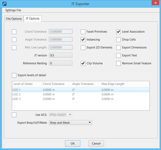
| Chord Tolerance
|
Used to set the chord tolerance of the output mesh.
It is in master units. The smaller the number, the finer the mesh will be. The
chord tolerance is applied before the angle tolerance.
|
| Angle Tolerance
|
Used to set the maximum angle for the mesh elements.
The smaller the angle, the more detailed the output will be. You should not set
this to a value greater than 45 degrees.
|
| Min. Line Length
|
Used to set the minimum line length that can be
exported. It is in master units. This is useful for eliminating points. Because
a point is a zero-length line, a value of zero can be used to eliminate points.
In the *.jt file that stores your export settings,
this value is stored under
"Point Tolerance".
|
| JT version
|
Used to set the JT version to be used for exporting
the file. The default is 9.5.
|
| Reference Nesting
|
Used to set the reference file nesting depth. A
value from zero (0) to five (5) can be used. The default is one (0).
|
| Facet Primitives
|
If on, facets are added to primitive shapes. If off
(default),
AECOsim Building Designer 3D primitive shapes are
exported as JT primitive shapes.
You should not need to use this option unless your
data includes primitive shapes that were not generated by
AECOsim Building Designer.
|
| Instancing
|
Cells with the same name are treated as shared
cells.
- If Instancing is
selected, then cells and shared cells in DGN file will be stored only once in
the JT file, even if they had been placed multiple times in the DGN file.
- If Instancing is
not selected, then cells and shared cells that had been placed multiple times
in the DGN file will be placed and stored separately in the JT file.
The default is on. It is recommended that you leave
it this way because it will reduce the file size and increase performance.
|
| Export 2D Elements
|
If on, 2D planar shapes are exported as 2D elements.
If off (default), 2D planar shapes are exported as faceted surfaces.
This option should be used only when 2D elements are
needed in the JT file.
|
| Clip Volume
|
If on, all the DGN data, including the files and
models are exported as a facet set. All the references are merged into a single
JT file.
|
| Level Association
|
If on, level node is added to the tree of JT
hierarchy structure.
|
| Drop Cells
|
If on, nested cells and shared cells are dropped and
treated as basic geometry elements and the hierarchical structure of the cells
is removed. This reduces the size of the exported JT file.
|
| Export Dimensions
|
If on, dimension elements are exported.
|
| Export Text
|
If on, text and text node elements are exported as
PMI (Product Manufacturing Information) notes.
|
| Remove Small Feature
|
If on, removes small features such as holes of size
lesser than the value set in the
Chord Tolerance setting.
|
| Export levels of detail
|
If on, surface and solid entities are faceted by
high, medium, and low precision and exported as three level of details, namely
"Lod 1",
"Lod 2", and
"Lod 3". You can set the tolerance values for
each level of detail in the list box below this check box.
|
| Use ACS
|
If on, allows you to select an ACS from the drop-down
list. The geometry is exported with respect to the coordinates of this ACS.
|
| Export Brep/ULP/Mesh
|
If on, allows you to export solid entities such as
SmartSolids and feature solids as one of the following:
- Brep and ULP
- ULP Only
- Mesh Only
- Brep and Mesh
- Brep, Mesh and ULP
|