Surface Definition Alternative
The computational grid is a surface (made up of cells) that defines how overland flows will behave. The computational grid has four aspects (grid layers) that you can adjust per cell: Elevation, Manning’s n, SCS CN, and Impermeability Fraction.
Grid Adjustment layers allow you to use shapefiles to adjust the various aspects of the computational grid. For example, you can use a building shapefile to raise elevations of grid cells occupied by building polygons.
Navigation
Select the [2D Modeling] tab on the ribbon and click the Surface Definition button.
Settings
There are two fields located at the top of the form: Terrain Model and Active Grid. The default for these fields is <auto>. You only need to choose a specific Terrain Model or Grid if you have more than one defined in your hydraulic model.
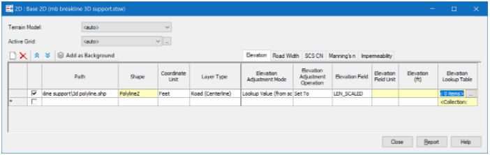
Grid Adjustment Layers Table
The Grid Adjustment Layers table allows you to use any number of external shapefiles to adjust the various aspects of the computational grid.

- New – Add a new row to the table.
- Delete – Delete the selected row(s).
- Shift-Up/Shift-Down - Use the shift-up/shift-dn buttons to control the order that adjustment layers are processed. The rows at the top of the table take precedence over rows that are lower down.
- Add as Background - Allows you to add the Adjustment Layer shapefile as a Background Layer so you can visualize it.
There are five tabs located along the top-right of the table: Elevation, Road Width, SCS CN, Manning’s n, and Impermeability Fraction. These tabs allow you to specify adjustment settings associated with that aspect of the computational grid.
- Use – The first column contains a checkbox which allows you to control if the row will be used when generating the Computational Grid.
- Path – The full path to the adjustment layer shapefile. Click the […] button to interactively browse out and select a shapefile.
- Shape – The shape-type of the shapefile that you selected (Polyline, PolylineZ, Polygon, PolygonZ). This is a read-only field and will be populated after you choose a shapefile.
- Coordinate Unit – The unit of your shapefile (the unit to be used when reading shapefile geometry).
- Layer Type – The type of layer your shapefile represents. The choices vary depending on whether you choose a Polyline or Polygon shapefile. The available choices for Polyline shapefiles are Breakline, and Road (Centerline). The available choices for Polygon shapefiles are Void, Adjustment Area, Building, Road, and Land Use (see the Layer Types section below for more details on each of these).
- <Aspect> Adjustment
Mode (/Road Width Mode) – Allows you to choose how you would like to provide an
adjustment value.
- <None> – Choose this if you do not want to adjust this aspect.
- User Defined Value – Choose this to provide a single adjustment value to be used for every record in the shapefile.
If you would like to use values contained in your shapefile to make adjustments, you have two options:- Value (from source) – Choose this to use values in the shapefile as is as the adjustment value.
- Lookup Value (from source) – Choose this when you want to map the value in the shapefile to the desired adjustment value (e.g., If your building shapefile contains values like one-story, two-story choose lookup value to map that to 14’ and 24’ respectively). See the <Aspect> Lookup Table section below.
- <Aspect> Field – The field in the shapefile that contains the adjustment values. (Only applies when the adjustment mode is Value (from source) or Lookup Value (from source)).
- <Aspect> Field Unit – The unit of the values in the Field that you chose. (Only applies when the adjustment mode is Value (from source)).
- <Aspect> Value – The adjustment value you would like to use. (Only applies when the adjustment mode is User Defined).
- <Aspect> Lookup Table – Allows you to map values in your shapefile to adjustment values you would like to use. Click the […] button to define your lookup table. (Only applies when the adjustment mode is Lookup Value (from source)). See also Lookup Table Form.
- Elevation Adjustment Operation – Controls how elevation values will be applied. Choices are: Add, Subtract, or Set (to raise, lower, or directly assign the elevation of the target cells respectively).
Layer Types
- Void – Void cells will be ignored during the FLOOD calculation.
- Breakline – Use this to adjust cell elevations for representing things like swales or walls. Note: You can use PolylineZ shapefiles to automatically adjust breakline elevations based on the x,y,z geometry.
- Land Use – Use this for adjusting SCS CN, Manning’s n, and/or Impermeability fraction in areas that represent grass, dirt, gravel, etc.
- Road (Centerline), Road, Building – Use these for adjusting any aspect (Elevation, SCS CN, Manning’s n, and/or Impermeability fraction).
- Adjustment Area – Use this for adjusting any aspect (Elevation, SCS CN, Manning’s n, and/or Impermeability fraction) for areas that do not fit into any of the other layer type categories.
Notes
Point shapefiles are not supported for Adjustment Layers. If you would like to make point-based adjustments, you can create point Adjustment Elements (by laying them out or importing them using ModelBuilder).
Defaults for Manning’s n, SCS CN, and Impermeability Fraction can be specified on the Grid element. Initial elevation values come from the terrain model.