2D Coupling Limitations
- Coupling
Channels: Channels represented in 1D are coupled to overland grid
surface using the Generate Grid operation. During grid generation, the in-bank
portion of the channel burns void cells into the grid and assigns the left and
right bank elevations correspondingly. To avoid user notifications pointing to
an unsuccessful coupling of a channel, the channel should be large enough to
successfully burn in its footprint upon the grid.
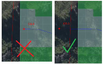
The channel should burn in a swath of void cells that is at least one cell wide. The void cells must share a cell face (horizontally or vertically neigbor) with another void cell.
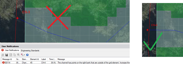
A cross section node cannot overlay the last active grid cell in a computational grid. You will have to move the cross section further outside or inside the grid.
Tributary channel networks can be burned into the grid. They must be dendritic, and no more than two channel links can share a cross section node at its downstream end.
Horizontally (zero) sloped channels have trouble burning into the grid at this time.
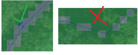
It is best that a channel have a perpendicular intersection with the edge of the grid to minimize discretization error effects..
- 2D
Ponds: Ponds and their connected hydraulic structures are solved as
part of the 1D system. The user will be warned if the cross sectional top
surface area of the pond is not comparable to its burned in footprint upon the
2D grid. The top elevation of the pond is assigned to the boundary cells that
border the pond’s voided footprint, which leads to a few limitations. For the
pond to accurately overtop, the elevations of these cells relative to the
terrain in proximity.
If one bank of the pond is higher (i.e. levee) supplement the accuracy of the grid with a breakline.
Where a pond and channel are connected, the pond’s bank elevation will prevail with its assignments of elevation onto the active cells of the grid in the vicinity.
- 2D
Inlets: There are some known limitations with the modeling of
coupled inlets. Typically, on-grade inlets have directed surface flows defined
by gutter link connections in a 1D simulation. An inlet can only capture flow
from the surface, and interface with one grid cell. All else being similar, the
same on-grade inlet will capture less in a 2D simulation because the surface
flows in the vicinity are much more distributed. There may be much less flow
upon the surface of that one grid cell. Therefore, it is best to simulate
inundated on-grade inlets as in-sag inlets. When deep flood waters exist,
in-sag functionality and a head-based capture curve will govern. Also, it may
be best to simulate a large inlet opening (large than the grid cell size) with
multiple nodes.
The amount of flow that a coupled inlet can capture is not only surface limited, but system limited as well. The capacity of the underground drainage system will cap how much the inlet can potentially intercept. One ongoing instability with inlets is the situation where the piped system is near capacity, some flow is intercepted at the inlet and combined with other inflows.
At the next time step, the system is full and no capture (or even upwelling) occurs in the next time step. A graph of flow captured at the inlet illustrates the oscillating nature of the system when it is near capacity.
Another known phenomenon is the inability of on-grade inlets to capture flow if the surface is inundated with standing water (as on-grade inlets operate as a Q vs Q rating curve in SWMM). We have yet to morph these inlets to an in-sag configuration (into an equivalent h vs Q curve in SWMM). This will better simulate interception of standing water, after surface waters recede and the piped system has capacity.