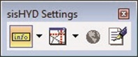
The following functions can be activated using the toolbox:
Object info
 Drop-down list for setting the
desired object information for the info tool:
Drop-down list for setting the
desired object information for the info tool:
Bubble
- Menu entry – Meaning
- Object – Shows the name
of the highlighted network object
- Results – Displays the
names and the results of the highlighted network object and associated
calculation
- The object information
refers to the object in the snap distance of the cursor.
Note: Use this feature
to access object information using the graphic, without having to open
associated technical data dialog.
Object
tracking
 Status indication for object
tracking, with which object tracking is switched on/off. When switching off the
emphasis is removed automatically from the diagram.
Status indication for object
tracking, with which object tracking is switched on/off. When switching off the
emphasis is removed automatically from the diagram.
- The emphasis of
objects always takes place in the model of the active view.
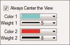
- The settings for
object tracking are reached using the arrow of the drop-down element:
- Always Center in View –
If this field is marked, each object is represented in the center of the view,
so the design detail of a view is moved. Otherwise sisHYD on switches the
detail of the view if the object lies outside of the detail.
- If more than one
object is involved in the emphasis, the centroid all objects of the enclosing
rectangle is centered.
- Color 1, Weight1 – The
general color or line strength for emphases determines.
- Color 2, Weight 2 – In
the case of emphasis of several objects special objects with the additional
color/line strength are marked. This option comes with selections and profile
plots to carrying.
Note: Object tracking
works hand in hand with the sisHYD dialog system. If object tracking is
activated, each data set selection of network objects leads to the marking of
the objects in the diagram. That is valid similarly for selections and profile
plots. See
Selections and
Profile
plot.
 Display Background Maps –
Switches the view of the background maps on or off.
Display Background Maps –
Switches the view of the background maps on or off.
- The basic map
appendix is not deleted from the design file, only the display is switched on
or off. The menu option is only selectable if a basic map is present for the
active model.
- Read-only Mode On/Off –
Status display for the read-only mode, which can be used to switch between
read-only mode and the regular write mode.
 – Symbol for write protection on
the dialog masks in the menu "components", "regulation" and "network
calculation".
– Symbol for write protection on
the dialog masks in the menu "components", "regulation" and "network
calculation".
 – Symbol for unrestricted access
and data change.
– Symbol for unrestricted access
and data change.