Bridge Component Layout Dialog Box
The Bridge Component Layout dialog box allows you to define the physical location, span information, bearing (skew), abutments/pier information, deck width and offset from alignment. The stationing for the beginning-of-bridge (BB) and the end-of-bridge (EB) is also defined in this dialog box. To open the Bridge Component Layout dialog box, click the Layout button on the Geometry tab.
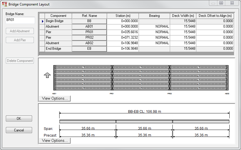
The Bridge Component Layout dialog box is used to define the physical location of superstructure connections. The physical location of these connections is specified using a stationing value from a common datum. The bearing of the superstructure connection is specified using an N-S degrees-minutes-section E-W value. You may also use the keyword NORMAL to denote a normal or radial connection, or the commend SKEW x.x where x.x is a positive or negative skew (from a normal) angle. The connection between the superstructure and abutments and bents is always assumed to be a roller support making the entire model a continuous beam model.
The Ref. Name attribute refers to the unique name of an abutment or pier defined in the Abutment/Pier Cap properties dialog box. Precast/Prestressed Girder checks the value of the stationing of connection items and marks items with equal stationings in red. The exception to this check is for the beginning-of-bridge and the end-of-bridge. The OK button becomes disabled until all red stationings have been corrected.