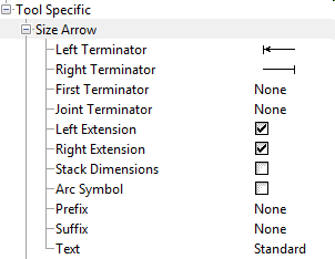
Understanding Tool Settings and Terminator Settings
The Advanced tab of the Dimension Styles dialog lets you define settings for each dimensioning tool. Since AutoCAD's dimension styles are very limited, most of these settings are not preserved when the DGN file is saved to DWG. However, the Left Extension and Right Extension settings are preserved. For the Arrow Size tool, the Left and Right Terminator settings are also preserved as follows:
- The Left and Right terminator settings on the Advanced tab, under the Tool Specific category, use symbols that are defined on the Terminators section. For example, if the Left terminator is defined with an arrow, it uses the Arrow symbol defined on the Terminator section. Terminator defined as Default or Cell are converted to shared cells when the file is saved, since AutoCAD terminators use blocks. The DWG format does not support the Symbol setting.
- If the Left and Right terminator settings are defined as arrows or strokes, then these settings are preserved when the file is saved to DWG.
- If the Left and Right
terminator settings use different terminator symbols (for example, Left is set
to arrow and Right is set to stroke), these settings are preserved.
Once the file is saved to DWG, the cell that defines the symbol for the left terminator is listed next to Arrowhead on the Terminators section of the Geometry tab. The left (Arrow) setting corresponds to the AutoCAD 1st Arrowhead setting (Dimension Settings). Likewise, the cell that defines the symbol for the Right terminator is listed next to the Stroke setting on the Geometry tab, under the Symbols option. The Right (Stroke) setting corresponds to the AutoCAD 2nd Arrowhead symbol.
- If the Left or Right Terminator uses the origin or dot symbol, the appearance of the symbol is maintained when the file is saved to DWG. However, the settings for these symbols are not preserved in the Advanced tab.