| Hole Axes
|
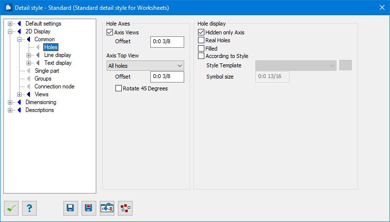
Settings for Drill Hole Axes.
|
| Axes View
|
When checked, the axis is depicted at a view on the
drill hole.
|
| Offset
|
Here, you specify the excess length of the axis
beyond the outside edges of the shape.
|
| Axes Top View
|
At a plan view on the drill hole the two axes
(horizontal and vertical) are depicted.
In the selection list, you can specify whether all
holes, only the visible holes or the invisible holes have to be displayed or
whether there has to be no display at all.
|
| Offset
|
Here, you specify the excess length of the axis
beyond the drill hole depiction.
|
| Rotate 45 Degrees
|
When checked, the two axes lines are rotated by 45°
to prevent that they overlap with dimension lines or others.
|
| Hole Display
|
Sets the Drill Hole Depiction.
|
| Hides only Axes
|
The hidden (invisible) drill holes are depicted
using a dotted line in plan view.
Otherwise, only the axes are depicted if these are
chosen for display. However, if you selected ‘Old Standard’, the axes are
always displayed.
|
| Real Holes
|
The holes are depicted according to their diameter
as either circular holes or hidden edges.
Otherwise, only the axes are displayed if these
are chosen for display.
|
| Filled
|
The hole depicted is completely filled.
|
| According to Style Template
|
The drill holes are displayed with a depiction which
can be defined freely. Thus it is possible to get your own depictions (e.g.
true to no scale or symbolic), too, depending on the current hole diameter for
the application of different standards and special cases.
- Style – The
desired hole style template for depiction. Create a hole style template in the
function for hole depiction and just load it here. Use the neighboring button
to get direct access to the Hole Display Style dialog for the creation of hole
style templates.
- Symbol
Size – The symbol size according to the hole style template.
|