Used to align a component or an entire construction
group relative to a specific plane or coordinate system.
The workflow involves specifying two coordinate systems,
which are then aligned to each other. Movement and rotation are applied to the
selected parts. You can set the coordinate systems with points or surfaces. The
point of origin is always regarded as the bottom point of the surface.
| Setting | Description |
|---|
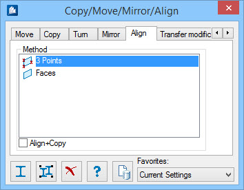
| Method
|
Selects how the planes are defined.
-
3 Points – Specifies a starting position
by selecting the object origin, then points on the X and Y axes. Then specifies
the new position by selecting the origin and points on the X and Y axes.
-
Faces – Uses one element surface. Select
the element at an edge adjacent to desired surface. A color coded display of
the surfaces becomes available for selection. The parts are then aligned
according to the specifications. The origin points become coincident.

1)
Original position, 2) Desired position. The first shape is aligned to the other
shape as a copy. It is moved and rotated at the same time.
|
| Align+Copy
|
When on, a copy of the component part is created.
The copy is then realigned. When off, the original part is realigned.
|