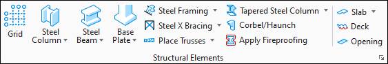
Tapered Steel Column
 Used to place tapered
columns. A tapered column is one that is represented by one section size on one
end and a different section size on the other end. A tapered column transitions
smoothly from one end to the other; there are no irregularities as such being a
single section size for six feet, then tapering the last 24 feet to a smaller
or larger section size at the end.
Used to place tapered
columns. A tapered column is one that is represented by one section size on one
end and a different section size on the other end. A tapered column transitions
smoothly from one end to the other; there are no irregularities as such being a
single section size for six feet, then tapering the last 24 feet to a smaller
or larger section size at the end.
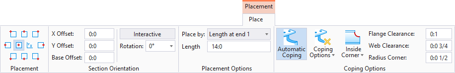
Placement tab
| Setting | Description | ||||||||||||||||
|---|---|---|---|---|---|---|---|---|---|---|---|---|---|---|---|---|---|
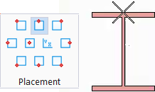
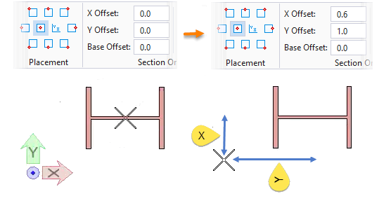
| Placement | Defines the location of the baseline relative to the member section by selecting from the drop list items. The attachment point dynamically updates on the pointer as the Placement icons are selected. | ||||||||||||||||
| Offsets: |
|
||||||||||||||||
| Interactive | When on (highlighted), an additional data point is required to place the member. The member appears to spin about the member line as the cursor moves around the screen. Rotation angle is calculated from the input point and the member is created with that angle. The contextual Placement tab settings is updated with the calculated angle and the Interactive option is disabled to place the next member with the same Rotation angle. | ||||||||||||||||
| Mirror | Typically used for member sections whose axis is not symmetric about its Y axis (for example, angles, channels, or zees). When on, an identical member is constructed, but in a mirror-image/flipped orientation. When off, mirroring already applied is removed. | ||||||||||||||||
| Rotation: |
Entered directly or selected from a drop down list
of common angles between minus 180° and plus 180°.
Note: The specific
entries are defined in the
Design File Settings Dialog's
Locks settings category.
|
||||||||||||||||
| Place by |
Determines the method of placement.
|
||||||||||||||||
| Length | Used to enter values for the various Place by methods. | ||||||||||||||||
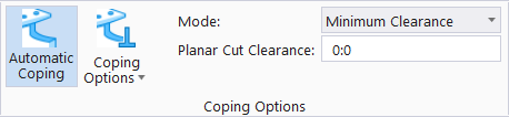
 Automatic Coping Automatic Coping
|
When on, enables automatic coping as steel members are placed connected to other steel members. When off, the Coping Options and Inside Corner options are also disabled. | ||||||||||||||||
 Cope to member connected by
AccuSnap Cope to member connected by
AccuSnap
|
Fits the member using the coping settings Flange Clearance, Web Clearance, Inside Corner and Radius Corner around the selected connecting member. | ||||||||||||||||
 Cope to any interfering member Cope to any interfering member
|
Fits the member using the coping settings Flange Clearance, Web Clearance, Inside Corner, and Radius Corner around all members in the vicinity of the member end. | ||||||||||||||||
 Trim to any interfering member Trim to any interfering member
|
Fits the member using the coping settings Planar Cut Clearance which sets a gap between two connected members. | ||||||||||||||||
 Cope normal to member line Cope normal to member line
|
Copes the end cut on a connecting member perpendicular to the member's center line. Selecting Cope normal to member line changes the settings available on the tab: | ||||||||||||||||
| Inside Corner |
Creates a relief on the inside corners of the
cope. The available types are illustrated on the split button:
 Plain,
 Round, or Round, or
 Rathole.
|
||||||||||||||||
| Flange Clearance | Maintains a space between the placed member web and the connected member flanges (for I beams). The clearance amount is entered in the available value field. | ||||||||||||||||
| Web clearance | Maintains a space between the placed member web and the connected member web. The clearance amount is entered in the available value field. | ||||||||||||||||
| Radius Corner | Sets the size of the round Inside Corner treatments. | ||||||||||||||||
| Mode | Enabled when is selected. | ||||||||||||||||
| Planar Cut Clearance | Enabled when is selected. |

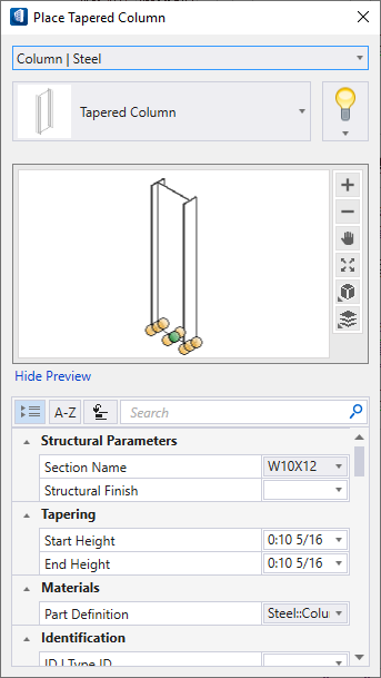
Tapered Column Properties
| Setting | Description |
|---|---|
| Catalog Type Selector | Used to select from available Catalog Types. Selections made here updates the Catalog Item Selector combo box. |
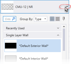
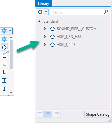
| Catalog Item Selector |
Used to select from available
Catalog Items. The
Catalog Item Selector combo box contains
several options and settings designed to make it easier to find the exact
catalog item you need to place/change.
The
Catalog Item list also includes user
defined assemblies, and RFA catalog items, if any.
|
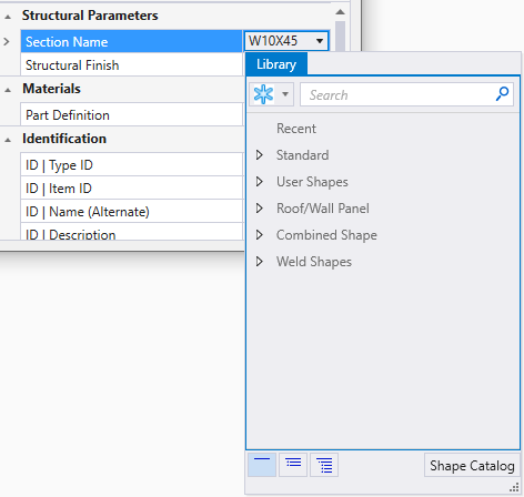
| Catalog Tools |
A split button located to the right of the
Catalog Item Selector contains tools to
assist with managing catalog data prior to placement of selected catalog items.
Note: The
Save Catalog Item and
Save Catalog Item As... tools perform
administrative tasks on DataGroup System catalogs. Administrators and users may
want to hide the tool icons to avoid incidental or unwanted changes to their
firm's dataset by setting the user configuration variables
BB_CATALOGITEM_ADMIN_IN_PLACECMDS
and
BB_CATALOGITEM_SAVEAS_IN_PLACECMDS to "0", respectively.
|
| Preview |
Displays the selected catalog item in the preview
window. This display changes and the preview updates as various options are
chosen. The preview also changes dynamically with some of the
prominent settings on the Placement tab, e.g Height, Rotation angle, etc. A
right-click in the Preview opens a
Show/Hide Viewing Tools option menu:
|
| Properties list - toolbar |
Used to manage catalog item properties during
placement or modification. Catalog item properties define the catalog item
instance in the model, and are accountable in the DataGroup System data
management tools. You can place a catalog item with its default property values
or you can change property values as needed, place an instance in the model,
and optionally save the changes to the catalog.
The Properties combo box contains tools for sorting and searching the properties list:
|
| Tapering | |
| Structural Parameters |
|
| Materials |
|
| Identification | Lists identification properties for the active catalog item type. |
| Fire Resistance | Lists fire rating properties based on agency fire safety tests and classifications. |
| Thermal Transmittance | Lists the thermal properties to apply to the active catalog item. |
| Construction Phase | Lists design and construction phase properties for walls such as New Construction, Future Construction, and Items to be Moved. |
| Structural Location |
Used to identify the location of Structural column
members in your model. The included Structural property
Column Location allows you to query and
report locations of columns relative to active grid systems. The locations of
columns are reported in the Schedules dialog.
For instance:
|
| IFC Override | Lists IFC properties not automatically mapped to DataGroup System properties that can be manipulated for export. |
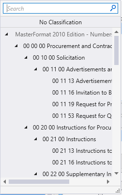
| Classification | Building Classification Systems are supported by the DataGroup System. MasterFormat, OmniClass, and UniFormat property values can be associated with any Building element. Click the Value cell to open the Classification System selection combo box. The combo box is populated with selected classification system property values. It can be resized by clicking on the combo box's bottom right corner. Search for properties by name. Search results are displayed in the classifications hierarchy. Double click a property to select it. This action also closes the selection menu. The selected property displays in the selected classification system property value (on the Properties list). |
| LEED Parameters | Lists several common Leadership in Energy and Environmental Design properties used to identify compliance of the active catalog item. |
| Structural Data |
|
 (
( (
( (
( (
( (
( (
( (
( (
( (
(


 (
( (
( (
(

Use the Catalog_Type and Catalog_Item arguments to key-in the desired catalog item saved in the active DataGroup System catalog to pre-populate the tool settings. For instance STFPLACE FORM TAPERED "Steel Beam" Beams where "Steel Beam" is the catalog type and Beams is the catalog item.