| Grid System Settings
|
Defines floor among
the disciplines and specify whether to include reference floor or not.
Additionally, it applies default Grid template annotations and set minimum
grid line extension value.
- Use Floor Discipline —
Selects
All or one of the available building
disciplines, among:
- Architecture
- Structural
- Mechanical
- Electrical
The grid settings apply to the active floor in selected
discipline. This option is useful where grids may need to be created to service
a particular discipline. It creates Grids for only those floor definitions
which have the corresponding discipline value. (Based on the discipline
enumeration available in the floor manager, which is a user extendible list.)
- Exclude Reference Floors —
When set to
Yes, excludes the reference
floor. The Grid System will only take into consideration the primary floor
definition and will exclude and ignore the reference floor definition. When set
to
No, all floor definitions
are used and Grids will be created for all floor definitions. It is not
uncommon for Floor Manager to contain numerous reference floor definitions for
other purposes.
- Grid
Template — Applies the default DGNLib template available at the
location set by the configuration variable
BB_GRID_TEMPLATE_DGNLIB.
Note: Undefined
state of
MS_DGNLIBLIST_ELEMENTTEMPLATES
prevents the Grid Systems settings contained in
GridTemplate.dgnlib
from being found.
- This can be fixed by adding the following
configuration statement in an appropriate CFG file:
- MS_DGNLIBLIST_ELEMENTTEMPLATES >
$(BB_GRID_TEMPLATE_DGNLIB)
- Adding it to the WorkSpace CFG;
Building_Examples.cfg, is one option. If you have a Custom Configuration, the
Standards.cfg in that Custom Configuration would be the most appropriate
location.
Selecting
Manage Templates opens the
Element Templates dialog where the definition of the
Grid Annotation and
Settings used to display the Grid within
a model or used in the production of an external grid model through the
Create/Update Grid Models option. It is also used in the generation of the preview
and any transient representation.
- Minimum
Grid Line Extension — Sets the shortest distance allowable between
label bubble and the end of the grid line. This is the minimum extension value
defined for the grid lines. Disabled for Sketch
Grids.
|
| Grid Labels
|
Sets label format and their order to suit regional
conventions. This option allows you to define the default labeling format as
either alpha or numeric. (A,B,C… or 1,2,3… ) and the direction of labels.
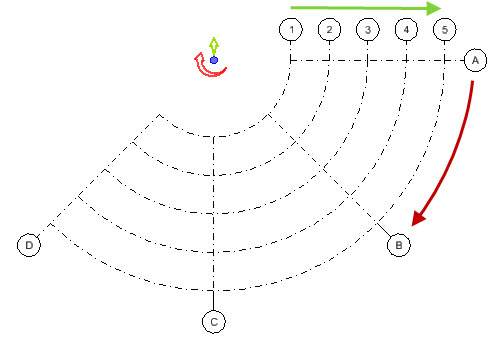
In practice, Grid labeling requirements differ
region wide to or even project to project. The
Label Direction options allows
you to define the direction in which the grid is defined to accommodate the
appropriate labeling sequence.

Right to Left / Bottom to
Top
|

Left to Right / Bottom to Top
(Default)
|

Right to Left / Top to Bottom
|

Left to Right / Top to Bottom
|
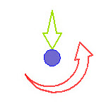
Counter clockwise,
Inwards
|
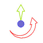
Counter clockwise,
Outwards
|
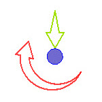
Clockwise, Inwards
|

Clockwise, Outwards
|
Example of
Counter clockwise, Outwards
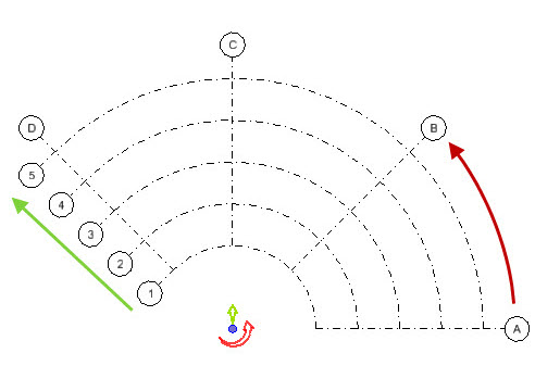
Example of
Clockwise, Outwards
In case of inwards types, the label numbering direction of
circular gridlines starts from outermost grid line and increments towards
innermost.
- Label
Vertical / Radial — Sets the label format either to alpha character
or numeric, auto sequenced in incrementing order. Pick one from the list:
- A, B,
C...
- 1, 2,
3...
- Custom...
- Label
Vertical / Radial Direction — Sets the vertical or radial direction
of the labels assigned to in grid layout.
- Left
to Right (for Orthogonal) / Counterclockwise (for Radial)
- Right
to Left (for Orthogonal) / Clockwise (for Radial)
Disabled for Sketch Grids.
- Label
Horizontal — Sets the label format either to alpha character or
numeric, auto sequenced in incrementing order. Pick one from the list:
- A, B,
C...
- 1, 2,
3...
- Custom...
Applicable to Orthogonal grids.
- Label
Horizontal Direction — Sets the horizontal direction of the labels
assigned to in Orthogonal grid layout.
- Bottom to Top
- Top
to Bottom
Disabled for Radial and
Sketch Grids.
- Exclude
Label Characters — Enter characters (alpha or numeric - as defined
for format), separated by a comma delimiter to skip it from labeling of grids
and in any automated sequencing of the label. This is useful when a certain
character could confuse its impression, e.g. F over E, O over Q etc., practiced
by various CAD standards.
|
| Grid Label Display
|
Sets label display placement and alignment.
Settings are disabled for Sketch
Grids.
- Display
Label on Top / Bottom / Left / Right — Sets to display or not the
label on respective side. Option toggles between:
- Display Label on Elevations —
Sets the display and position of the label on an Elevation dynamic view. Set
one of the options among:
- Off - Prevents
the gridlines of the given grid from showing up in Elevation dynamic views.
Since each grid has its own settings, you can therefore turn off the display of
individual grids in an Elevation dynamic view. This is in contrast this with
the global
Show Grid System setting in the View
Attributes dialog - Building Panel General tab, which prevents gridlines from
all grids from showing up in the Elevation dynamic view.
- Top
- Bottom
- Top
& Bottom
- Align
Linear Labels — When
On, grid labels are aligned to the
orthogonal grid system regardless of the
Min/max Extents defined. When
Off, grid labels
attach to their parent grid
lines at the selected
Min/max Extents.
- Align
Radial Labels — When
On, grid labels are aligned to the
radial grid system regardless of the
Min/max Extents defined. When
Off, grid labels attach to their parent
grid lines at the selected
Min/max Extents.
|
| Dimensions
|
Sets whether or not to
display the dimension with grid labels, the dimension style and the offset
values. Settings are disabled for Sketch Grids.
- Display
Dimension — When set the dimensions are displayed as set to the
side of the grid label. The options are:
- Always —
Displays the dimension of the grid lines at default position.
- With
Grid Labels — Displays the dimension along the grid labels.
- With
Top/Left | Top/Right | Bottom/Left | Bottom/Left ... Grid Labels —
Displays the dimension at specified side option of the grid labels.
- Never —
Displays no dimensions.
- Dimension
Style — Applies predefined dimension style from the pull-down
options.
- Dimension
Text Height Override — Applies a desired value over the default 0:0
1/8 to set override to dimension text height.
- Dimension
Plan Offset — Sets the value of plan offset for the dimensions.
- Dimension
Elevation Offset — Sets the value of elevation offset for the
dimensions.
|
| Save As Default Settings
|
Saves as default option, allowing the Grid System
setting to be saved both to the Local and Global storage. Remains pre-set by
default when there is no grid systems defined and the Grid Systems dialog is
empty.
|
| Apply to All Grid Systems
|
Applies the current Grid System Settings to All Grid
Systems, irrespective of selections. This option does not apply setting to the
Global settings, unless Save As Default is also selected.
|


