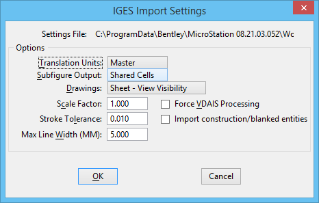
IGES Import Settings Dialog
| Setting | Description |
|---|---|
| Translation Units | Sets how IGES file units are equated to
OpenBuildings Speedikon
working units, as follows:
|
| Subfigure Output | Sets how
subfigures are translated, as follows:
|
| Drawings | Sets how IGES drawing entities and entities with
views visible attributes are translated:
Note: Sheet DGN
files are created with the same filename as the model DGN file with the
extension
".Sxx," where
"xx" is the drawing sheet number. For example,
the first sheet DGN file for
"test.dgn" would be
"test.s01," the second
"test.s02," and so on. If the
MS_SHEETSEED configuration
variable is set, the sheet DGN file is created from the seed file it points to.
Otherwise, the sheet DGN file is created by copying the header data from the
model DGN file.
Note: See
Drawing sheets and view
visibility for general information about drawing sheets and view
visibility.
|
| Scale Factor | Sets the scale factor that is applied to imported
IGES entities; can be used to tailor the translation to accept geometry from
systems that generate data at a different scale or in a different coordinate
system.
By default, the scale factor is set to 1.0 (no scaling is performed). |
| Stroke Tolerance | Sets the maximum deviation, in Translation Units,
between the actual curve and the approximating line segments used to represent
excluded arc, curve, B-spline curve, or B-spline surface entities in the DGN
file.
If any of these IGES entities are excluded in the Exclude IGES Entities dialog (opened by choosing Settings > Exclude IGES Entities in the Import IGES File dialog), they are approximated by line segments, referred to as strokes, in line string or shape elements. If stroke tolerance is decreased, the number of segments and the size of the DGN file is increased and the approximation quality is finer. If stroke tolerance is increased, the number of segments and the size of the DGN file is reduced and the approximation quality is coarser. |
| Maximum Line Width | Sets the IGES line weight (thickness) in
millimeters (mm) that is assigned to line weight 31. The other
MicroStation line weights are assigned
thicknesses that are proportional to this value.
An inverse relationship exists between the Maximum Line Width and the MicroStation line weight that is assigned to a line from the IGES file. Consider a line in an IGES file that has a thickness of 2.5 mm:
Thus, increasing the Maximum Line Width setting decreases the MicroStation line weight assigned to a given line. |
| Force VDAIS Processing | If on, the IGES file is assumed to be VDAIS-compliant. VDAIS is a set of guidelines for using IGES established by the German automobile industry. |
| Import construction/blanked entities | If on, imports IGES entities which are marked as construction or blanked entities. |