| Show Hierarchy
|
When on, displays a tree that shows the active file
and references that are directly attached to it. References that have other
references attached to them (nested references) are listed in black text, and
references that do not have attached references are listed in gray text.
If a reference in the hierarchy has a nesting depth
value of 1 or more, you can:
- click on the (+)
sign and expand the hierarchy display.
- select the
reference. When you do this, the References list box updates to include only
the references that are attached to the selected reference.
When the tree is turned off, you can use the arrow
button next to the Show Hierarchy icon to list the active file and any
references that are directly attached to it. As in the tree, if you choose a
reference that has attached references, the References list box updates to
include only the references that are attached to the selected reference.
|
| Attach Reference
|
Opens the
Attach Reference dialog, which lets you attach a model to
the active model.
|
| Clip Reference
|
Uses a boundary, such as an element or fence, to clip a
reference. The area of the reference outside the boundary is not displayed.
|
| Mask Reference
|
Covers a
portion of a reference that is inside a boundary. More than
one clipping mask can be specified for a model.
|
| Delete Clip
|
Deletes a clipping mask.
|
| Set Ref Back Clip Z
|
Sets the back clipping plane, which is a boundary used to
clip a 3D referenced model. The position of the clipping plane is measured
along the view's z-axis. Only the portion of the reference in front of the back
clipping plane is displayed.
|
| Set Ref Front Clip Z
|
Sets the front clipping plane, which is a boundary used to
clip a 3D referenced model. The position of the clipping plane is measured
along the view's z-axis. Only the area behind the front clipping plane
displays.
|
| Reload Reference
|
Reloads and redraws a reference, which lets
you see changes that have been made to the referenced model since it was last
attached or reloaded.
|
| Move References
|
Moves the references.
|
| Copy References
|
Copies the references.
|
| Scale References
|
Resizes references.
|
| Rotate References
|
Rotates references.
|
| Mirror Reference
|
Reflects a reference about a horizontal or vertical axis.
|
| Copy/Fold Reference
|
Copies the selected reference, then attaches a view of the
reference by folding it about an orthogonal axis or a line defined.
|
| Set Reference Presentation
|
Sets options for
displaying references. These options include Wireframe, Hidden Line,
Filled Hidden Line, and three types of shading.
|
| Detach Reference
|
Detaches the reference from the active model.
|
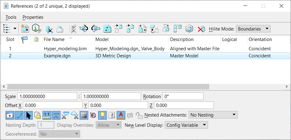
| Hilite Mode
|
Controls whether the selected references are
highlighted and surrounded by a border.
- None — Selected
references are not highlighted in any way.
- Boundaries — Places
a dashed border around selected references.
- Hilite — Highlights
selected references.
- Both — Places a
dashed border and highlights selected references.
|
| References list box
|
Lists the references attached to the active model
file, or to the nested reference selected in the hierarchy.
- To change the
columns of reference information displayed, right-click on the row of column
titles. Use the menu to turn columns on or off.
- To sort the list by
a column, click on the column title. For example, click on Slot to sort the
list by slot number.
For each reference, these columns are displayed by default:
- Slot - A unique
number assigned to the reference.
To edit a slot number, slowly double-click on
the number, then key in a new number. If you key in a slot number that is used
by another reference, the slot numbers are exchanged.
- Status - Shows
whether a reference has been modified by another user since it was read in. You
may want to reload references that have been modified.
- Activate Status -
Shows whether a reference is activated for in-place editing or is deactivated.
A black dot indicates it is activated. A gray check mark indicates it is
deactivated.
- If the selected
reference is neither activated nor locked, double-clicking in this column
activates the reference.
- If the selected
reference is activated, clicking in this column deactivates the reference but
leaves it locked.
- If the selected
reference is activated, double-clicking in this column deactivates the
reference and releases the lock.
- If the selected
reference is locked but not activated, clicking in this column releases the
lock.
- If the selected
reference is locked but not activated, double-clicking in this column activates
the reference.
- File Name - The file
containing the reference.
- Model - The model
selected for the reference.
- Description - The
description of the reference.
- Logical - The
logical name for the reference.
Since the same model can be attached many
times, the logical name helps you distinguish between references.
- Orientation - The
view of the attached model.
You can change the orientation of the reference.
On clicking this cell reference, a window similar to Orientation in
Reference Attachment Properties dialog appears where you can
change the view.
The column turns red if the orientation is not
available for the attached model.
The clipping and clip mask settings of the
previous orientation are saved for the next orientation. These settings are
retained until you create a new Orientation setting.
- Presentation - The
presentation method (for example, wireframe). The Reference Presentation dialog
opens when you click the cell in this column.
- Visible Edges -
(Drawing or sheet model only) Sets the visible edges display option. Clicking
the cell in this column, opens a visible edges window. The Visible Edge
drop-down list in it has following options:
- Display (icon) - If
on, the reference is displayed.
Key-in:
REFERENCE SET DISPLAY=0|1
<filename>
Setting 0 or 1 also may be input as off|on or
false|true.
- Snap (icon) - If on,
you can snap to elements in the reference.
Key-in:
REFERENCE SET SNAP=0|1
<filename>
Setting 0 or 1 also may be input as off|on or
false|true.
- Locate (icon) - If
on, you can identify (select) elements in a reference for construction
purposes.
Key-in:
REFERENCE SET LOCATE=0|1
<filename>
Setting 0 or 1 also may be input as off|on or
false|true.
- Treat Attachment as
Element for Manipulation (icon) - If on, the reference can be manipulated with
the standard manipulation tools.
Key-in:
REFERENCE SET TREATASELEMENT=0|1
<filename>
Setting 0 or 1 also may be input as off|on or
false|true.
The
other columns that can be displayed are:
- Named Group -
Identifies a named group used to limit the elements displayed in the reference.
- Element template -
(Applicable to SHP file attachments only) Assigns the selected template to the
attached SHP file.
When this column is displayed, you can select a
reference, then click on the column to open the Element Template window. Select
the element template from this window. For further details, refer the
Using GIS Files section.
- Revision - If Design
History is on in the referenced model, lets you select the revision used for
the reference. If the original revision of the reference no longer exists you
must reattach the reference.
- GeoCS - The
geographic coordinate system identifier, if the reference has one. The contents
are red if a GCS exists but the reference is attached without a georeferencing
attachment mode.
- GeoCS Description -
Displays the description of the geographic coordinate system, if the reference
has one.
- Transparency (icon)
- Sets the degree of transparency to be applied to the reference.
When this column is displayed, you can select a
reference, then click on the column to open the Reference Transparency dialog.
Select a preset value for transparency, use the slider, or key in a value to
adjust the degree of transparency. The value may vary from 0% to 100%, with a
value of 0% that indicates no transparency at all, while a value of 100%
indicates almost complete transparency.
Key-in:
REFERENCE SET TRANSPARENCY=value from 0.0 to 1.0
<filename>
For example, a value of 0.1 gives a
transparency of 10%.
When elements, references, and levels have
different transparency values assigned to them, then effective transparency is
calculated and applied on them.
If elements, references, and levels are
assigned different transparency values, then
effective transparency is applied on them.
- Priority (icon) - If
on, the units in the active model and those in the referenced model are used to
calculate the appropriate scaling factor, so that the reference scale reflects
a true real-world scale.
Where 3D references are attached to a 2D model,
this setting is disabled for the 3D references.
Key-in:
REFERENCE SET PRIORITY=value from -5 to 5
inclusive <filename>
- True Scale (icon) -
If on, the units in the active model and those in the referenced model are used
to calculate the appropriate scaling factor, so that the reference scale
reflects a true real-world scale.
- Scale Line Styles by
Reference Scale (icon) - If on, custom line style components (for example
dashes) are scaled by the reference scale. If off, custom line style components
are not scaled.
Key-in:
REFERENCE SET SCALELINESTYLES=0|1
<filename>
Setting 0 or 1 also may be input as off, on, false, or
true.
- Clip Back (icon) -
If on, allows a back clipping plane to be applied to a 3D referenced model.
- Clip Front (icon) -
If on, allows a front clipping plane to be applied to a 3D referenced model.
- Display Raster
References (icon) - If on, raster references that are attached to the reference
are displayed.
Key-in:
REFERENCE SET DISPLAYRASTERREFS=0|1
<filename>
Setting 0 or 1 also may be input as off, on, false, or
true.
- Ignore Attachment
When Live Nesting (icon) - Lets you control the display of nested attachments
when working in a DWG or DXF file, where live nesting is always on and there is
no limit to nesting depth.
Key-in:
REFERENCE SET IGNOREWHENNESTING=0|1
<filename>
Setting 0 or 1 also may be input as off|on or false|true.
- Use Lights (icon) -
During rendering, the source lighting cells present in the active model are
always considered. Any source lighting cells located in references are ignored
unless the Use Lights setting is turned on for the reference.
Key-in:
REFERENCE SET USELIGHTS=0|1
<filename>
Setting 0 or 1 also may be input as off|on or false|true.
- Plot As 3D (PDF)
(icon) - (PDF printer driver only) When on and the PDF printer driver is used,
the reference is plotted as 3D data in Universal 3D (U3D) format. The 3D
content will contain any visualization data and settings that already exist
within the design file such as lights, materials, and animations or
flythroughs. When the PDF file then is viewed in Acrobat 7, the document
contains a 3D view with controls that let you rotate, zoom in/out, or walk
through the 3D model, as well as running an animation, if any.
Key-in:
REFERENCE SET PLOTAS3D=0|1
<filename>
Setting 0 or 1 also may be input as off|on or false|true.
- Use Active
Annotation Scale (icon) - If on, makes the reference's annotations use the
active model's annotation scale.
- Application Locked
(icon) - If on, the reference has been locked in place by the source
application. The Move, Rotate, Scale and Mirror commands are disabled. By
default it is off. Users cannot change this setting.
Note: The quotation
marks symbol
" in the columns means that the reference is
redundant - it appears as a nested reference in more than one place in the tree
at the same position, scale, and rotation, with the same clip boundary.
|
| References list box right-click menu
|
When you right-click a reference in the references
list box, you can directly access options that are available in the Tools and
Properties menus, as follows:
- Items from the Tools menu — Attach,
Detach, Reload, Exchange, Open in New Session, Activate, Deactivate, Move,
Copy, Scale, Rotate, Merge Into Master, Make Direct Attachment, Create Drawing
Boundary, Clip Boundary, Clip Mask, Delete Clip.
- Item from the
Properties menu — Presentation and (Attachment) Settings. Also contains Update
From Saved View and Push to Saved View settings from the Set Reference
Presentation tool settings window.
These
right-click options, not available on the menus, are also available: Add Link
to Element, Update From Saved View, and Push to Saved View.
|
| Information panel
|
Displays and controls settings for a selected
reference.
- Scale — Displays
and sets the ratio of master units in the active model to the master units in
the attached model.
- Rotation — Displays
and sets the rotation for the selected reference. In a 2D model, it is the
rotation in the X-Y plane (z-axis). In a 3D model, it is the rotation about the
axis of one of the following Standard Orientations: Front, Back, Right, Top,
Bottom, or ISO. When you modify the rotation from the information panel, you
set the value directly and you are changing the rotation about the current
origin point of the reference. That origin point is:
- The center
point of the fence if the reference was clipped with a fence.
- The center
point of the view if the reference was placed using a saved view.
- The origin if
the reference was placed with either Coincident or Coincident World, and not
clipped.
The Rotation Reference tool allows you to
specify an additional rotation to apply and the point about which the rotation
is to be applied.
- Offset — Displays
and sets the distance between the global origin of the reference from the
global origin of the parent file, measured in units of the parent file. If the
parent is 2D, Offset X and Y values are displayed. If the parent is 3D, Offset
X, Y, and Z values are displayed.
- Attachment settings
icons — The information panel icons correspond to columns in the References
list box to icons on the
Reference Attachment Properties dialog. If an icon is
pressed, the setting is on. Click the icons to switch the settings on or off.
For more information on an icon, see the description for the corresponding
column in the References list box.
If you select multiple references that have
different settings, the icons representing different settings are shaded. For
example, if one of the selected references has True Scale enabled while the
other selected reference has True Scale disabled, the True Scale icon is
shaded.
- Display Hidden
Elements From Visible Edge Cache icon — This icon is enabled only for cached
references that contain hidden elements. If on, the hidden elements of the
cached reference are displayed in blue color and the remaining elements are
displayed in gray color.
- Nested Attachments list box — Displays
and sets how nested references (references attached to references) are handled
for the selected attachments.
Note: When
working in a DWG or DXF file, live nesting is always on, and there is no limit
to nesting depth. Therefore the Nested Attachments and Nesting Depth controls
are disabled. To control the display of nested attachments, you must open the
reference as the active model and use the Ignore Attachment When Live Nesting
setting for its attachments.
- Display Overrides list box — Controls
how override settings are saved for nested references. For a specific nested
reference, overrides let you control the settings for reference display,
locate, snap, raster reference display, and level display.
- Allow - If you
change a nested reference’s settings in its parent file, those settings will
override the settings that were set in its master file until those settings are
changed in the master file. Once the nested reference’s settings are overridden
in the master file, the file settings will not match and the files will operate
independently from each other. The nested reference’s settings will be set one
way in the parent file, and another way in the master file.
Key-in:
REFERENCE SET NESTOVERRIDES=allow
- Always - A
nested reference’s settings in its master file always override the parent
file’s settings for the nested reference. If you change a nested reference’s
settings in its parent file, those settings will not take precedence over its
settings in the master file.
Key-in:
REFERENCE SET NESTOVERRIDES=always
- Never - If you
change a nested reference’s settings in its master file, those settings will
never override the settings that were set in its parent file. After changing a
nested reference’s settings in its master file, closing, and reopening the
file, the settings will revert to the way they were set in its parent file.
Key-in:
REFERENCE SET NESTOVERRIDES=never
- Nesting Depth —
Sets the number of levels of nested references that are displayed. Child
references can have their own referenced models, which, in turn, can have more
referenced models, and so on.
If Depth is set to 0, only the selected model
is attached to the master model; models referenced to the selected model are
ignored.
Not accessible when Nested Attachments is set
to No Nesting.
When working in a DWG or DXF file, live nesting
is always on, and there is no limit to nesting depth. Therefore the Nested
Attachments and nesting Depth controls are disabled. To control the display of
nested attachments, you must open the reference as the active model, and use
the Ignore Attachment When Live Nesting setting for its attachments.
Key-in:
REFERENCE SET NESTDEPTH=<integer between 0 and
99>
- New Level Display — Specifies whether
a reference displays new levels. The setting also applies to new levels in
nested references that are attached to the reference.
- Config Variable
- New levels in the reference are displayed according to the setting for the
MS_REF_NEWLEVELDISPLAY
configuration variable.
Key-in:
REFERENCE SET
NEWLEVELDISPLAY=fromconfig
- Always - New
levels in the reference are always displayed.
Key-in:
REFERENCE SET
NEWLEVELDISPLAY=always
- Never - New
levels in the reference are never displayed.
Key-in:
REFERENCE SET
NEWLEVELDISPLAY=never
The criteria for the level being considered as
new is different for non-synchronized and synchronized saved views:
-
Non-Synchronized saved view case — A level is considered new to the reference
if the time the level was created is newer than the time the reference was
attached. This is called as time stamp. The time stamp of the reference is not
changed until you do a save settings to the active model, that is the model
containing the reference. Additionally, the New Level column in the Level
Display dialog displays a check indicating the level creation time is newer
than the time stamp of the reference model.
- Synchronized
Saved View case — In this case new level is not dependent on the time stamp of
the reference model, but the time the saved view was created. The time stamp of
the saved view is modified when the saved view is updated. You cannot view
whether a level is new to the saved view.
In each of the above cases once the time stamp
of the container (reference or saved view) is equal to or newer than the level
creation time, the level is no longer considered new.
- Georeferenced — Sets the georeference
mode. When a reference is attached in Reprojected mode, the current Reference
Reprojection Settings are copied into the reference attachment and stored so
every user who opens the master file uses the same reprojection settings and
thus, gets the same results.
When a reference is attached in Geographic –
AEC Transform mode, it calculates the linear transform that gives the best
approximation to the results of performing the full reprojection algorithm, if
the active model and the reference have geographic coordinate systems. For
further information, see the Orientation setting in the Reference Attachment
Properties dialog.
- path — Shows the full specification
for the reference, including the directory.
- Right-click menu — Controls the
display of items in the information panel.
|
| Tools menu
|
The Tools menu provides tools for working with
references. Many of the tools can also be accessed by right-clicking on a
References list box item.
|
| Tools > Attach
|
Opens the
Attach Reference dialog, which lets you attach a model to
the active model.
DIALOG
REFERENCE
ATTACHURL
|
| Tools > Detach
|
Detaches the reference from the active model.
|
| Tools > Detach All
|
Detaches all referenced models from the active model.
|
| Tools > Reload
|
Reloads and redraws a reference, which lets you see changes
that have been made to the referenced model since it was last attached or
reloaded.
|
| Tools > Reload All
|
Reloads and redraws all references, which lets you see
changes that have been made to the referenced models since they were last
attached or reloaded.
|
| Tools > Exchange
|
Opens the selected reference, retaining the same
view configuration.
XD=
REFERENCE
EXCHANGE
|
| Tools > Open in New Session
|
Opens the selected reference — file and model — in
a new session.
REFERENCE
NEWSESSION
|
| Tools > Activate
|
Activates the selected reference for in-place
editing. A black dot indicates it is activated. Only references that are not
open for editing in another session can be activated.
REFERENCE
ACTIVATE
[
filename
]
REFERENCE
REFERENCE
[
logical_name
]
|
| Tools > Deactivate
|
Deactivates the selected reference so that you can
return to editing the active model. A gray check mark indicates it is
deactivated.
REFERENCE
DEACTIVATE
[
filename
]
REFERENCE
DEACTIVATE
[
logical_name
]
|
| Tools > Move
|
Moves references.
|
| Tools > Copy
|
Copies references.
|
| Tools > Scale
|
Resizes a reference.
|
| Tools > Rotate
|
Rotates references.
When Rotate is chosen, the Rotate Reference dialog
opens, letting you set the rotation angle(s).
|
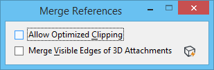
| Tools > Merge Into Master
|
Merges referenced models into the master DGN file.
REFERENCE
MERGE
|
| Tools > Make Direct Attachment
|
Promotes the nested attachment to a direct
attachment so it can be modified. The nested attachment becomes redundant with
the newly created direct attachment. Quotation marks under Display, Snap, and
Locate indicate a redundant attachment.
REFERENCE
MAKEDIRECT
When
specifying references with the key-in, you can use either * or all to
indicate all references. For individual references, you can give its logical
name, or the reference file name.
Note: When using the key-in to promote a nested
attachment to a direct attachment, you specify the path to the reference with
arrows consisting of the minus and greater than characters (->). For
example,
REFERENCE MAKEDIRECT parent->child.
Examples of arguments for the reference
makedirect key-in:
-
REFERENCE MAKEDIRECT *->child —
processes all nested references (first level of nesting) with logical name
child.
-
REFERENCE MAKEDIRECT parent->* —
processes all nested references of file parent.
Multiple attachments can be specified by
separating each with a space, such as
REFERENCE MAKEDIRECT parent->attach1
parent->attach2. Where filenames have spaces in them, the file
specification must be enclosed in quotes, such as
REFERENCE MAKEDIRECT parent->attach 1
parent->attach 2.
|
| Tools > Create Drawing Boundary
|
Opens the Create Drawing Boundary window. Click OK
to create a drawing boundary with the default drawing boundary name.
|
| Tools > Mirror Horizontal
|
Reflects a reference about a horizontal axis.
REFERENCE
MIRROR
HORIZONTAL
|
| Tools > Mirror Vertical
|
Mirrors a referenced model about a vertical axis.
REFERENCE
MIRROR
VERTICAL
|
| Tools > Clip Boundary
|
Uses a boundary, such as an element or fence,
to clip a reference. The area of the reference outside the
boundary is not displayed.
|
| Tools > Clip Mask
|
Covers a portion of
a reference that is inside a boundary. More than one
clipping mask can be specified for a model.
|
| Tools > Delete Clip
|
Deletes a clipping mask.
|
| Tools > Clip Front
|
Sets the front clipping plane, which is a boundary used to
clip a 3D referenced model. The position of the clipping plane is measured
along the view's z-axis. Only the area behind the front clipping plane is
displayed.
|
| Tools > Clip Back
|
Sets the back clipping plane, which is a boundary used to
clip a 3D referenced model. The position of the clipping plane is measured
along the view's z-axis. Only the portion of the reference in front of the back
clipping plane is displayed.
|
| Properties > Attachment
|
Opens the
Attachment Properties dialog, which sets
attachment information for the selected referenced models.
Note: The Attachment
Properties dialog also opens when you double-click a referenced model in the
list box in the References dialog.
|
| Properties > Update Sequence
|
Opens the
Update Sequence dialog, which changes the
display order for all operations involving the updating of the view windows.
|
| Properties > Adjust Colors
|
Opens the
Adjust Colors dialog, which modifies or adjusts the color
table for references.
REFERENCE
ADJUSTCOLORS
[
					 value, saturation,
						reference_specification
]
Note: The syntax
allows wildcards, matching both the reference filename and logical name, as is
the case for all
REFERENCE key-ins. For example,
keying in
REFERENCE ADJUSTCOLORS 80,50 floor*
adjusts the color table for all references that match the specification
floor* to 80% value, 50% saturation. If you omit the reference specification,
OpenBuildings Speedikon uses the selections in the Reference dialog, if any, or
otherwise, prompts you to identify a reference.
Note: The values
that you select are stored in the reference attachment element.
|
| Properties > Reprojection
|
Opens the Reference Reprojection Settings dialog,
which defines the reprojection settings for the selected reference(s). This
menu item is disabled if the Georeferenced mode is not set to Reprojected.
Note: References attached with earlier
versions of OpenBuildings Speedikon do not have a value for the
georeferenced mode. For compatibility with earlier versions of OpenBuildings Speedikon, such references are treated as
Georeferenced in Geographic - Reprojected mode if both the attachment and the
master model contain a geographic coordinate system.
|
| Properties > Hilite > Boundaries
|
Places a dashed border around the reference.
|
| Properties > Hilite > Hilite
|
Highlights the reference.
|
| Properties > Level Manager
|
Opens the
Level Manager dialog, which is used to manage levels for
the active model and its references.
|
| Properties > Level Display
|
Opens the
Level Display dialog, which is used to turn on and off
levels in the active model and its references.
|
| Properties > Presentation
|
Opens the Reference Presentation dialog, which sets
the display attributes of the selected referenced models.
All controls in
this dialog are similar to those on the
View Attributes dialog.
|
 Used to attach and
detach referenced models, adjust reference settings and select reference
tools.
.
Used to attach and
detach referenced models, adjust reference settings and select reference
tools.
.