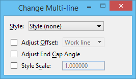
Change Multi-line
 Used to change a multi-line's attributes to the active multi-line definition, which can be set in the Multi-line Styles dialog.
| Adjust Offset by | Then the work line is | Illustration |
|---|---|---|
| Work Line | At offset position 0,0 as defined in the active multi-line definition (in the illustrations, the position of the dashed line). | |
| Center | Adjusted to be midway between the outermost component lines. If there is a component line at the center, the work line is superimposed on it. | |
| Maximum | Adjusted to be superimposed on the component line with the maximum Offset. | |
| Minimum | Adjusted to be superimposed on the component line with the minimum Offset. |
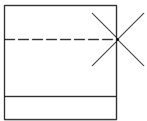

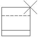

In the table, the illustrations for Maximum and Minimum show the pointer when drawing from left to right. Thus, the top component line has a positive Offset, and the bottom two component lines have negative Offsets.
| Setting | Description |
|---|---|
| Style | Sets the current multi-line style from a list of all available multi-line styles. |
| Adjust Offset | Sets the work line's position in the multi-line when placed and how the component lines are offset (see table above). The work line's position can be changed between placements of individual segments. Placing a multi-line in this manner, however, prevents you from using Association to associate vertices with other elements. If the Match Element Attributes tool is used to make the active multi-line definition match that of the multi-line in the design, the work line is assigned the offset 0,0. |
| Adjust End Cap Angle | If on, it adjusts the angle of the end cap according to the angle settings of activated style in multi-line styles dialog after changing the current selected multi-line style. |
| Style Scale | If on, the offset distances for the component lines are scaled by the amount shown. |
Tip: The active multi-line definition can be set to match a multi-line element with the Match All Element Settings (SmartMatch) tool.