Define Camera
 Used to set up a view for rendering, or to create saved views. This can be done interactively by manipulating the dynamically displayed view cone via handles at strategic points. Alternatively, you can use Define Camera for specific manipulations, and its settings window for precision inputs. To assist you visualize the design as you manipulate the camera, the viewing cone can be displayed in all other views.
You can access this tool from the following:
With Continuous View Updates turned on, the camera view updates dynamically as you manipulate the view cone in the other views. You can have your camera view displayed as a smooth rendered view as you position the camera.
The Define Camera settings window lets you display only those settings that you require. With the More/Hide button you can quickly display or dismiss the more settings group box. Within this group box, Show/Hide buttons let you expand only those settings that you wish to examine or modify.

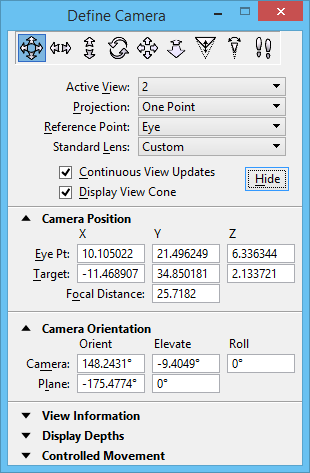
Fields in each of the settings update as modifications are made to the view cone. Alternatively, values can be input directly to the relevant settings.
When the Define Camera tool is used for the first time, in a design, it makes the current active view its Active View. This view becomes the camera view. You can use the Active View setting in the tool settings window to change to another view. If Display View Cone is turned on (in the tool settings window), then view cones appear in the other open views that display the same region of the design. These show the viewing extents of the camera view. The shape and features of the view cone depend on the Projection active at the time.
The tool settings for Define Camera apply to the viewing parameters of the active or camera view. You can change this view's parameters by typing values to the various fields. When you make changes to the view interactively, values in these fields update automatically. Interactive adjustments can be made via the view cone, or directly in the camera view using one of the Camera Action settings.
You can control the orientation of the view cone by positioning handles, either dynamically, or by entering values in the Define Camera settings. Circular orientation handles are provided to adjust the orient, elevate, and roll view settings.
To display the view cone, you must ensure that Display View Cone is turned on, in the tool settings window. When Continuous View Updates is turned on, the camera view updates dynamically as you modify the view cone, either interactively or via the tool options.
When you start the Define Camera tool, AccuDraw is off. You can activate it using the AccuDraw's shortcut key-ins — <T>, <S>, <F>, and <V>.
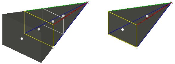
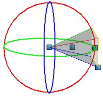
To assist you in relating the view cone to the camera view, it is color coded. In the view cone geometry, the red line equates to the top left corner of the camera view, the green line to the top right corner, and the two blue lines to the lower corners of the camera view. Rectangular shapes in the view cone display the:
- Back clip plane (grey) — if Back Clip is on in View Attributes for the camera view
- Target plane, and active depth (yellow)
- Front clip plane (white) — if Front Clip is on in View Attributes for the camera view
Handles at the centers of the three planes let you move them interactively, as follows:
- Moving the eye point handle does not affect the position of the target handle, and vice-versa.
- Moving the center handle (located midway between the eyepoint and the image plane handles) moves the whole view cone.
- Moving the image plane handle of the one point projection view cone lets you rotate the image plane independent of the eye and targets.
- Moving the handle at the lower left corner of the image plane lets you change the lens view angle.
- When moving the front clipping plane, it must be closer than the focal distance, and farther than 1/1000th of the Back Clip distance.
- When moving the back clipping plane, it must be farther than the focal distance and closer than 1000 times the Front Clip distance.
The circular orientation handles are also color coded as:
Where you know the exact coordinates at which you wish to place the eye point or target, you can use precision inputs.
| Setting | Description |
|---|---|
| Camera Action icons | The following Camera Action icons are used to make interactive adjustments in the view:
|
| Active View | Sets the view to be used as the camera view. |
| Projection | Sets the projection to display in the camera view. |
| Reference Point | Sets the point about which the camera manipulations are performed. |
| Standard Lens | List box that lets you select a standard camera lens, or to define a custom lens.
|
| Continuous View Updates | If on, the camera view is updated continuously as the view cone is adjusted, either graphically, or via the input fields. |
| Display View Cone | If on, the view cone, for the camera view, displays in all other open views that display the same portion of the design. |
| More/Hide button | Turns on (More) or off (Hide) display of other settings that may be adjusted in the camera view. |
| Camera Position | Sets the location of the camera and target.
|
| Camera Orientation | Sets the camera and image plane orientation. Camera — Defines the camera location. Plane (One Point projection only) — Defines the image plane orientation.
|
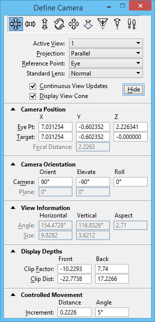
| View Information | Sets the viewing angles and aspect ratio.
|
| Display Depths | Sets the clipping planes for the camera view.
|
| Controlled Movement | Sets incremental limits, Distance and Angle, for controlled movement of the camera, target, or view cone. The maximum Distance increment is one-half the distance from the eye to the target. The maximum Angle increment is 45°. |


