Helix Feature


Used to create a helical-shaped parametric solid. It sweeps a selected profile (closed cell, closed line string, shape, complex shape, circle, ellipse, or closed B-spline) along a helical curve defined by height, radius and pitch settings. Tool settings let you define a helix of varying pitch, and right or left thread. A tolerance option lets you control the precision used in creating the helix. Larger tolerances result in rougher approximations of a smooth surface.
| Setting | Description |
|---|---|
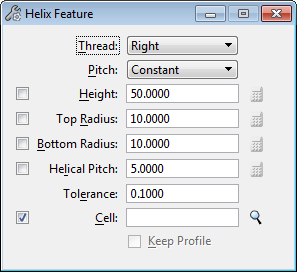
| Thread | Lets you define the helix to be Right or Left thread. |
| Pitch | Lets you set the pitch of the helix to be Constant or Varying. |
| Height | If on, defines the height of the helical solid. Otherwise, the height is defined graphically. |
| Top Radius | If on, defines the top radius of the helical solid. Otherwise, the radius is defined graphically. |
| Bottom Radius | If on, defines the bottom radius of the helical solid. Otherwise, the radius is defined graphically. |
| Helical Pitch | If on, sets the distance between the coils of the helix. Otherwise, the pitch is defined graphically. |
| Equation icons | Located adjacent to the Height, Top Radius, Bottom Radius, and Helical Pitch settings and is enabled when the relative setting is turned on. Opens a dialog that optionally lets you define each setting with variables. For more information, see Variable Driven Modeling and Constraints. |
| Tolerance | Sets the numerical tolerance used to compute the B-Spline surface. |
| Cell | If on, the active cell is projected. A new active cell can be typed in the field. |
| Browse Cell(s) icon | (Cell on only) Opens the Select Profile dialog, which lets you select a profile from the attached cell library, or from any shared cells present in the model. Where a dimension driven cell is chosen, you can edit its parameters. |
| Keep Profile | (Cell off only) If on, the original profile is retained in the model. |

