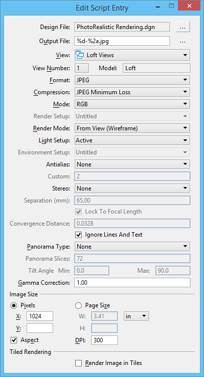
Edit Script Entry Dialog
Used to add a new script entry, or to modify an existing script entry.
When you pause the pointer over the Design File or Output File fields, a tooltip displays the full path to that file.
Any changes that you make in the Edit Script Entry dialog are applied immediately to the script entry in the Save Multiple Images dialog.
| Setting | Description |
|---|---|
| Design File | The name of the design file to render. The active design file is the default. To select a different file, click the Browse for design file icon (at right of the Design File name field), which opens the Select File to Render dialog. The controls are analogous to those in the Open dialog. |
| Output File | The name of the output file after processing the design file. This can be the actual file name, or you can use an Output File Name macro. By default a macro, with the selected file format's extensions, is inserted. To change the name or location of the output file, click the Browse for output file icon (at right of the Output File name field), which opens the Set Output File dialog. The controls are analogous to those in the Save As dialog. |
| View | Sets the source view group, or saved view to use.
Selecting a view also selects the associated model.
Icons differentiate view groups from saved views with icons, as follows: Indicates a view group. Indicates a saved view. |
| View Number | Option menu that lets you select the view. |
| Model | Displays the name of the model to which the selected view is associated. |
| Format | Sets the image file format. |
| Compression | Sets the degree of compression for an image file format. For example, compression options for a JPEG format image file are from Minimum Loss to High Loss. Greater compression is achieved as image quality is sacrificed: Minimum Loss yields the highest image quality and least compression; High Loss yields the poorest image quality and the greatest compression. |
| Mode | Sets the number of colors in the image file's color palette. The available options depend upon which Format is chosen. For example, Intergraph RGB supports only 24-bit color, while PICT supports 24-bit color, 256 colors, and grayscale. |
| Render Setup | Lets you select a render setup that is in the DGN file, or Untitled for the current settings. |
| Render Mode | Sets the rendering method — Wireframe, Visible Edge,
Filled Visible Edge, Smooth, Vue Ray Trace or Vue Path Trace. See
Introduction to Rendering for information about rendering
methods.
When a render setup is active, only those rendering methods display that are available for the selected render setup. |
| Light Setup | Lets you select a light setup that is in the DGN file, or Untitled for the current settings. When using Vue render, the brightness and contrast values can be stored in the light setup. |
| Environment Setup | Lets you select an environment setup that is in the DGN file, or Untitled for the current settings. |
| Antialias | Lets you select the degree of Antialiasing for the entry, or None for no antialiasing. |
| Custom | (Antialias set to Custom only) Controls the number of antialias samples per pixel. Must be a number which is a power of 2. The predefined values in the Antialias drop-down options corresponds to the following number of antialias samples: Use the Custom field to enter another value (number which is a power of 2) than the ones above. |
| Stereo | Renders a view with a stereo effect. Used for viewing with special red/blue filtered glasses. |
| Separation (mm) | Sets the measured offset between the two rendered images. Default is 65 millimeters. |
| Lock to Focal Length | If on (default), locks the convergence distance to the focal length. |
| Convergence Distance | Sets the point within 3D space where the two offset images converge. In front of this point, objects appear to come forward and behind the point, objects appear to recede. |
| Ignore Lines And Text | If on, restricts rendering processes to only those elements that include an area component: surfaces and all closed elements such as shapes, ellipses, and complex shapes. Conversely, all open elements, such as lines, arcs, text, and points, are not rendered (and therefore not displayed in rendered images). |
| Panorama Type | Sets the type of panorama that the script entry will
be saved as, if any.
|
| Panorama Slices | Defines the number of slices in the cylindrical
panorama.
This field is disabled (dimmed) when Cube is the selected Panorama Type. |
| Gamma Correction | Sets the brightness of the image in the file. The default value is 1; the valid range is 0.1 to 3.0. Increasing the Gamma Correction setting lightens the image; decreasing it darkens the image. |
| Pixels | If on, image size is defined in pixels along the X and Y axes. |
| Page Size | If on, image size is defined in physical dimensions for width (W) and height (H). Units for the dimensions (in, mm, or cm) are chosen from the option menu to the right of the width (W) field. |
| Aspect | If on, the aspect ratio of the selected view is
maintained.
That is, when Pixels is selected and you set the X or Y resolution, the remaining setting automatically is adjusted to match the view aspect ratio. Similarly, when Page Size is selected and you set the W or H dimension, the remaining setting automatically is adjusted to match the view aspect ratio. |
| DPI | Lets you define a dots per inch (DPI) value for your image. |
| Render Image in Tiles | (Panorama Type set to None only) If on, enables the tiled rendering process which breaks up the target rendering subject into a series of user-defined tiles. |

