Updates to Victaulic Catalog
A Typical Victaulic Groove Joint between piping components has both Male Groove Ends and then Connected using a Victaulic coupling
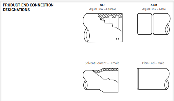
However, there can be cases where both ends are not grooved e.g. an adapter nipple with one end as grooved and other end is threaded.
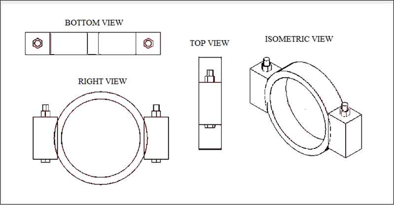
A typical Victaulic Cam and Groove Coupling is drawn in OpenPlant Modeler according to following mapping of the properties in Catalog\Spec mdb file
- Coupling
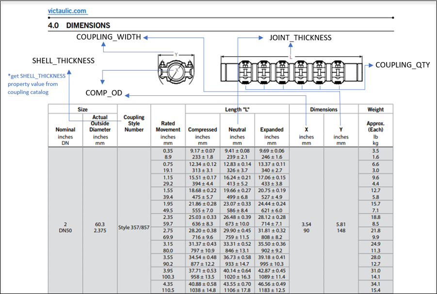
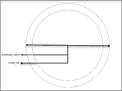
Width
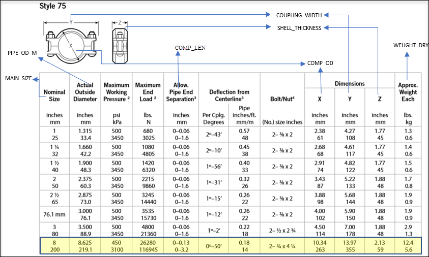
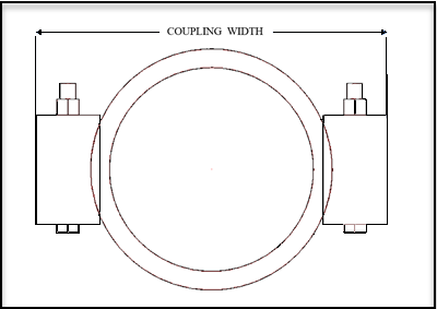
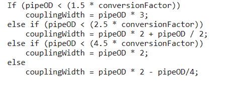
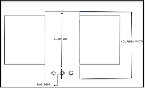
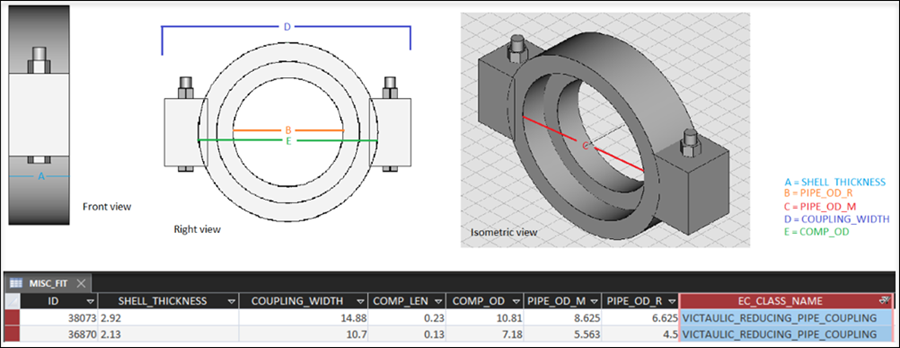
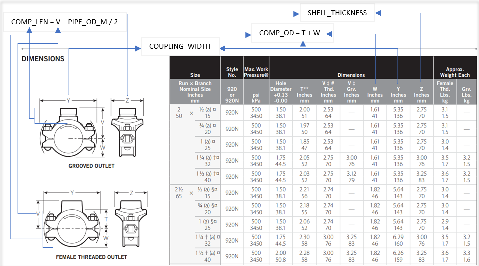
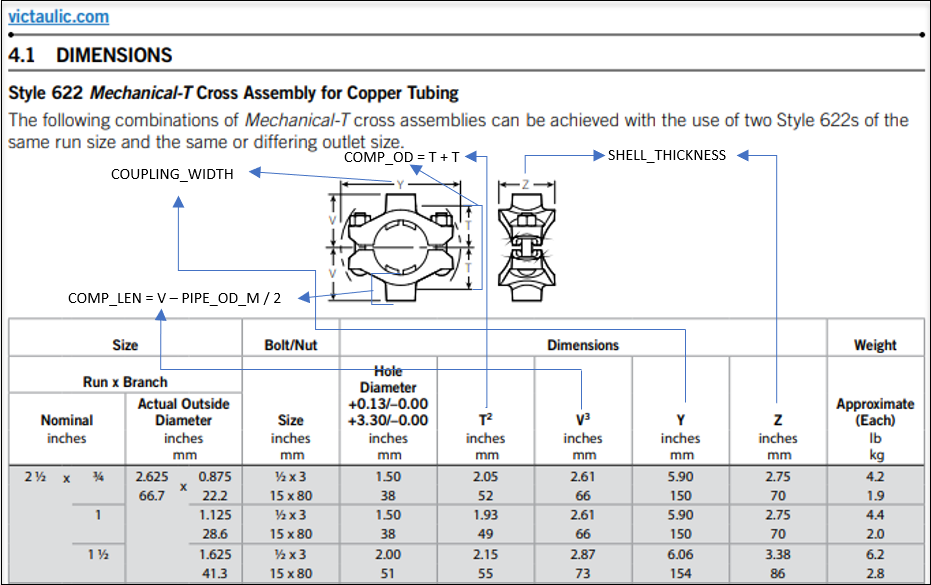
For COUPLING_WIDTH there is no field available in the spec to map this property. So, we create another field COUPLING WIDTH in the spec and create EC property with the same name in the 3d schema to read data from the spec.
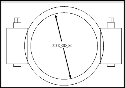
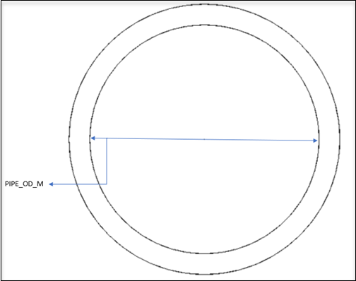
- PIPE_OD_M
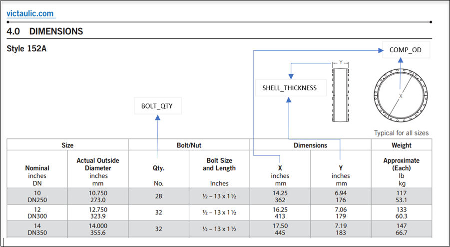
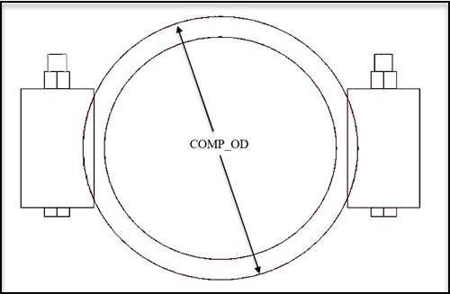
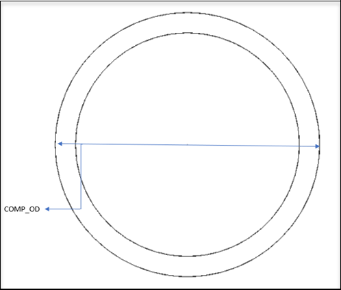
- COMP_OD
This field is mapped with the X dimension of the catalog and it represents the outer diameter of Coupling. The value of this file is 263 in the catalog.
If COMP_OD is zero or not defined in the spec we can get the value using the following conversion
cylinderOd = pipeOD + shellThickness;
if COMP_OD and COUPLING_WIDTH are equal, no slabs and bolts will be drawn in the coupling
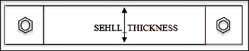
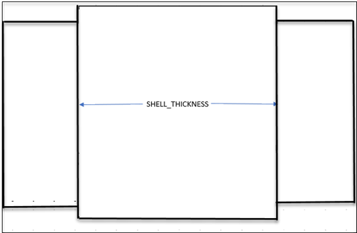
- SHELL_THICKNESS
This field is mapped with the Z dimension of the catalog and it represents the thickness of COUPLING. The value of this field is 59.
If SHELL_THICKNESS is zero or not defined in the spec we can get the value using the following conversion
shellThickness = pipeOD / 4;
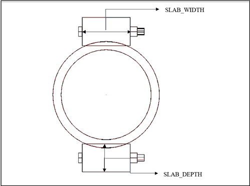
- Slabs
The slab that is attached with the coupling we calculate their dimension using known values (pipeOD, compOD, and couplingWidth).
SLAB_WIDTH
slabwidth = couplingWidth - compOD;SLAB_DEPTH
slabDepth = (couplingWidth - compOD) / 2 + (compOD - pipeOD) / 4;When we only have one slab
slabDepth = (couplingWidth - compOD) + (compOD - pipeOD) / 4; - NUT/BOLT
Nut/ Bolt properties not defined in the 3d schema, so we are calculating the dimension of these using SLAB dimensions
BOLT_DIA
boltDia = slabDepth / 4;BOLT_LEN
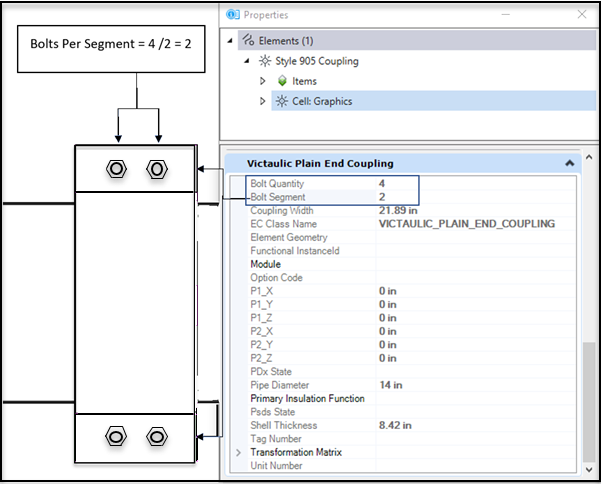
boltLen = slabwidth + (2 * boltDia);BOLT_QUANTITY
Total number of bolts in couplingBOLT_SEGMENT
The total number of slabs in coupling. Currently, we support up to two segments.if BOLT_QUANTITY and BOLT_SEGMENT both are 0, we set
boltQuantity = boltSegment = 2;and if BOLT_SEGMENT is not 0 but BOLT_QUANTITY is less than BOLT_SEGMENT or BOLT_QUANTITY is not divisible by BOLT_SEGMENT we set
boltQuantity = boltSegment;Bolts Per Segment
boltsPerSegment = boltQuantity / boltSegment;
List of Groove Profiles Supported in OpenPlant Modeler CONNECT
Apart from Standard\Original Cam and Groove System, following Groove profiles are now supported in OpenPlant Modeler . Their related components and Joints are now available in OpenPlant Modeler Catalogs and Schemas.
Victaulic Hole Cut System
Variables and Graphics\Placement updates
- OPM_MATCH_PROPERTY_MAP_MATERIAL - Added a New Variable OPM_MATCH_PROPERTY_MAP_MATERIAL to support different Material Combinations incase Material is added as a Matching criterion. Most of the Victaulic couplings are of Ductile Iron Material whereas Piping components material can vary. So, in order to allow placement of different Material Victaulic coupling on piping components this variable can be used.
- OPM_CUSTOM_AUTO_FIT_FILTER_PROPS - Set the value of this variable equal to MATERIAL. It matches the material for fittings to be placed through autofitting with Pipeline.
- OPM_AUTOFITTING_SELECTION_GRID_FOR_ELBOW - Added a new variable OPM_AUTOFITTING_SELECTION_GRID_FOR_ELBOW. Set its value to 1 to see the selection grid dialog for pipe elbow when placed through autofitting. By default, Washer\gasket is not part of Flange Groove Joint, its optional and user can add it if needed.
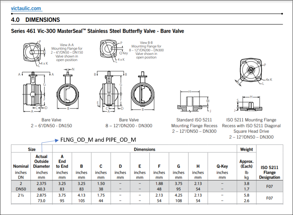
If you set the value B from the catalog as the outside diameter of the Butterfly valve, you will get the following graphics
Actual Outside Diameter value is set as the Outside Diameter of the valve. Victaulic Butterfly Valve series E125 has female end conditions, its outside diameter are as per set in the catalog.
Expansion Joint
- Style 355/355P
- Victaulic Mover
Expansion Joint
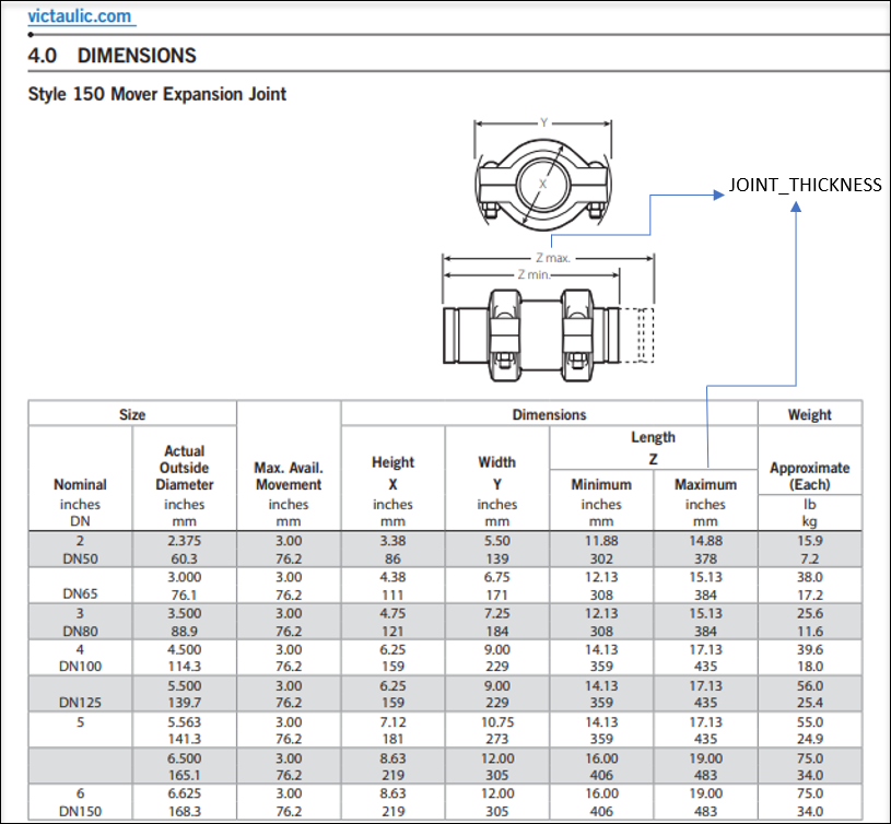
Style 150
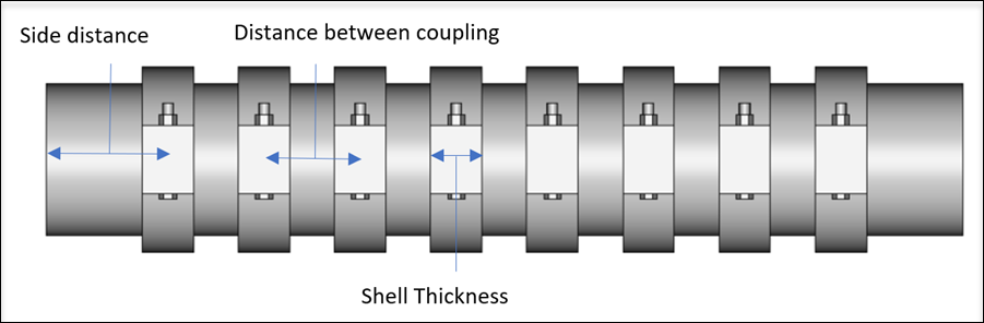
Shell Thickness
Shell thickness is the shell thickness/Z property of the specified coupling.if no value of coupling is given, shell thickness will be calculated as
if (0 == ShellThickness)
ShellThickness= pipeOD / 4;
if (shellThickness >= distanceBtwCouplings)
shellThickness = distanceBtwCouplings x 0.7;
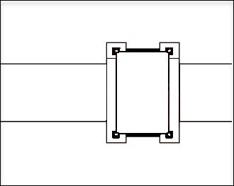
Side Distance & Distance between couplings
Side distance is the distance between side coupling and the end of the joint. Distance between coupling is mid to mid-distance between couplings.
Side distance and distance between couplings are calculated as:
if the coupling is greater than 1
sideDistance = (jointThickness / (couplingQuantity + 1.0) ) x 1.20;
distanceBtwCouplings = (jointThickness - (sideDistance x 2)) / (couplingQuantity - 1);
if the coupling quantity is 1distanceBtwCouplings = jointThickness / (couplingQuantity + 1.0);
sideDistance = distanceBtwCouplings;
Coupling Quantity
Coupling Quantity is the number of couplings in the joint. Each coupling will have 2 bolts and 2 segments.
if Coupling Quantity is equal to 0
if (0 == couplingQuantity)couplingQuantity = 1;
Joint Thickness
Joint thickness is the full length of the joint.
if joint thickness is 0
if (0 == jointThickness)jointThickness = 2 * mainPort.DiameterInMM;
- Expansion Joint
Coupling Style 152A
BOLT_QTY and BOLT_SEGMENT
These graphics are drawn when BOLT_QTY is greater than 0 and BOLT_SEGMENT is equal to 0.