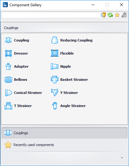
Used to place inline components including couplings and
strainers etc.
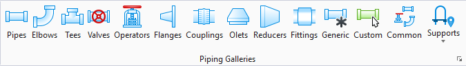
Accessed from the Piping ribbon.
The following gallery displays which can be left floating or
docked to the drawing area.
| Component
|
<Component Class> in
Placement Key In syntax (Mechaddin Place <Component Class> dsc=Piping)
|
Coupling

|
PIPE_COUPLING
|
Reducing Coupling

|
REDUCING_PIPE_COUPLING
|
Dresser Coupling

|
DRESSER_COUPLING
|
Flexible Coupling

|
FLEXIBLE_COUPLING
|
Pipe Adapter

|
PIPE_ADAPTER
|
Nipple

|
PIPE_NIPPLE
|
Bellows

|
BELLOWS
|
Basket Strainer

|
BASKET_STRAINER
|
Conical Strainer

|
CONICAL_STRAINER
|
Y Strainer

|
Y_STRAINER
|
T Strainer

|
T_STRAINER
|
Angle Strainer

|
ANGLE_STRAINER
|
Placement
Placement of inline type components usually consists of
the following common steps:
- Set the size and spec in
the
Standard Preferences dialog.
- Select an option from the
Couplings Gallery.
Note: If there is more
than one record in the specification that meets the criteria, you are prompted
to select a specific record from the
Spec
Record Selection dialog.
- Define the Placement Point
(Main Port, Run Port etc.) and settings in the Place Component dialog.
- Use the mouse to pick
placement and direction and rotation points.
Note: Generally these
type of components are placed either connecting to an existing length of pipe,
or inserted into a length of pipe.
Note: If connecting to
an existing component, then only placement and rotation picks are required.
Note: Expansion Joints are child class of Bellows.