How To Define a Support Drawing Template
OpenPlant Support Engineering
ships a default Support Drawing Template file which you can edit if desired, or save it under a different name and define new drawing areas if desired. The following procedure details how to add drawing areas to a template file.
-
Open the default Drawing Production Template (OPSE_DrawingProduction.dgn) located in the following directory:
C:\ProgramData\Bentley\OPSE\WorkSpace\Projects\%Project%\Dataset\seed\
- Set the current layer to DPTemplate and switch it on so you see the previously defined areas.
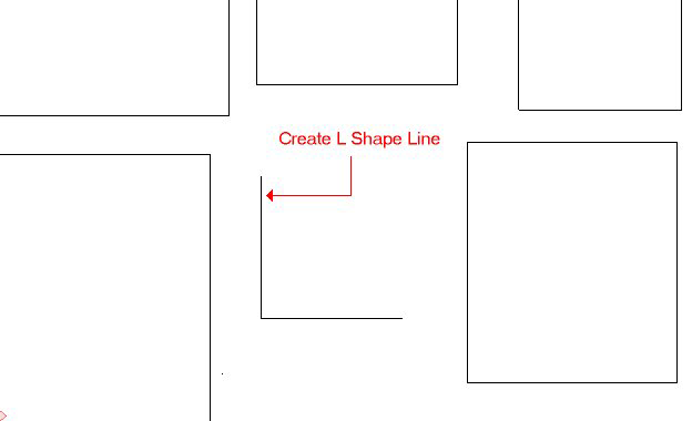
- Draw two connected MicroStation Lines in L shape of desired length and width.
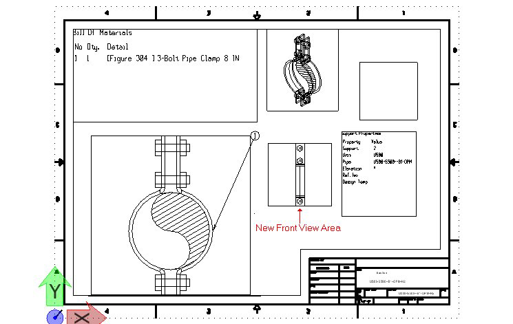
- Click on one of the area buttons (BOM, General Settings or Graphics Area).
- When prompted to select an object click on the line created in the previous step. It will create a rectangle you can place anywhere in the drawing area. Use the mouse to drag position the area correctly and left-click to place.
- Once you have placed the area, delete the L shape lines and position this rectangle where you want to keep.
- After editing the template you can switch off the layer again so that final drawing those area's will be invisible by default. Once the drawing has been saved, it will display the next time you generate a Support Drawing: