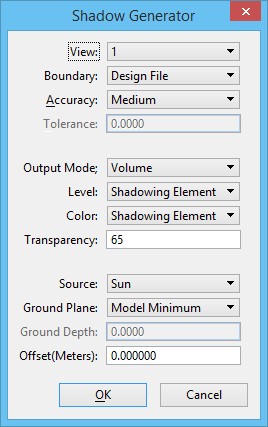
| View |
Used to determine the levels, reference files, etc., to be processed. If Boundary is set to View, only geometry within the view is processed. |
| Boundary |
Controls the geometry to be processed.
- Design File — Geometry within the entire model is processed.
- View — Geometry within the view is processed.
- Fence — Geometry within the fence boundary is processed.
- Selection Set — Only the currently selected elements are processed.
|
| Accuracy |
The shadow generation process approximates curved surfaces with polygonal facets. The Accuracy setting determines how accurately the facets approximate the underlying surface.
- Low, Medium, High — The Low accuracy setting produces a coarse mesh, but shorter processing time. High accuracy produces a more accurate representation at the expense of increased accuracy.
- To Tolerance — If To Tolerance is selected, an explicit accuracy value can be entered.
|
| Tolerance |
(Accuracy set to To Tolerance) Controls the maximum error (the precision) for the color shadow generation Lower tolerance values produce higher quality output at the expense of increased processing time. Tolerance values should be defined in master units. |
| Output Mode |
Controls the geometry produced to represent the shadows.
- Volume — Produces a surface that represents the outer limits of the shadows.
- Outline — Produces only the outline of the shadow boundaries.
|
| Level |
Controls the level of the shadow geometry.
- Active — Shadow geometry is created on the current active level.
- Shadowing Element — Shadow geometry is generated on the level of the element producing the shadow.
|
| Color |
Controls the color of the shadow geometry.
- Active — The active color is used.
- Shadowing Element — The color of the shadowing element is used.
- Shadowing Material — The shadow color is calculated from the material of the geometry that generated the shadow.
|
| Transparency |
Controls the transparency of the surfaces generated to represent shadow volumes. Values range from 1–100, default is 65. |
| Source |
Controls the shadow source.
- Sun — The Sun is selected to produce solar shadows.
- View — Used to produce shadows from the current view location; useful when doing line-of-sight studies.
|
| Ground Plane |
In order to control the placement of shadows on models which may not have the ground surface completely defined, an implied ground plane is used. Shadows that do not intersect any other geometry are terminated at this implied plane. The Ground Plane option controls the location of this plane.
- Model Minimum — Places the ground plane at the minimum depth for geometry in the model.
- Specified Depth — Places the ground plane at the depth specified in the Ground Depth field.
|
| Ground Depth |
(Ground Plane set to Specified Depth) The distance along the z-axis to the ground plane. |
| Offset (Meters) |
Used to offset the shadow geometry from the surface on which the shadow falls. Also used to reduce the display anomalies resulting from coincident shadow geometry. |