Add Component to Template
First, identify the desired component in the Component Browser.
Then, click on it once and move the cursor to the Graphical Editing View to position it.
Once it is positioned, left click to accept the positioning. Positioning components can only be done in some pre-defined location to avoid creating invalid templates. See the Components section for more details.
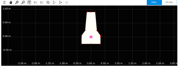
Graphical Editing View tools
The Graphical Editing View offers multiple productivity tools allowing rapid create and modify templates.

 Delete
Deletes the selected components. Notice that it is possible to select more than one component pressing the CTRL key on your keyboard.
 Navigation tools
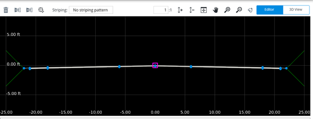
The navigation tools plan, zoom in, zoom out and fit the view.
 Mirror toggle
The mirror toggle modifies the behavior of the place components allowing placement of components on both sides of the template in one click.
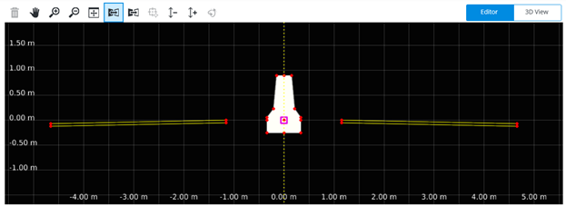
Note: If the template is not symmetrical on both sides it will not allow the components to be placed using this tool.
 Reflect toggle
The Reflect toggle modifies the behavior of the placement command allowing to flip a component while placing it.
Placing a component without this toggle on.
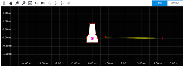
Toggling the Reflect will flip the component

 Set Origin
The Set Origin moves the template origin to another location. The Origin point of the template determines the alignment location in the cross section view.
A very common use of the Set Origin command is to place a central component such as the dual face barrier.
First place the barrier
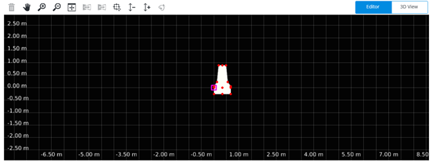
Then click the Set Origin tool and select the location to place the origin.
Left click to move the origin point.
 Scale Up/Down
The scale up and scale down commands are used to modify the vertical exaggeration inside the Graphical Editing View.
 Rotate View
Click and drag to rotate the view of the model. Right-click to revert back to the previously active measure or select tool.