Using Drawing Boundaries and Named Boundaries to Automate Dynamic Views
The drawing boundary and named boundary features can be very useful in automating dynamic views. Following example explains the same.
To Use Drawing Boundaries and Named Boundaries to Automate Dynamic Views

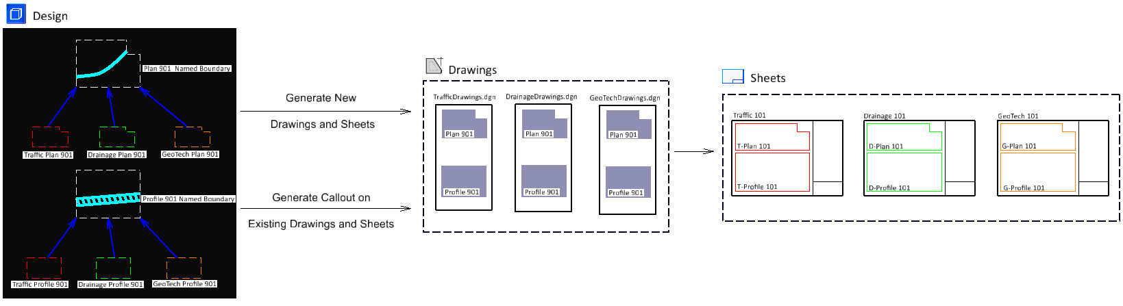
Consider a scenario where you have a roadway, say I-95, and you want the plan and profile of each part of the roadway. You will require to create multiple saved views of each part with different levels turned on or off for different purposes such as traffic plan, drainage layout, and geographical details. You may then want to place each of these views in sheet models to plot them. Following workflow will help you in achieving this easily and efficiently.
- Create seed saved views and drawing boundaries for plan and profile in your WorkSet's DGNLib file. The drawing boundary can be of custom shape created using the
Place Drawing Boundary
tool.

- In the design model, activate the Place Named Boundary tool and make the following settings in the Place Named Boundary tool settings window:
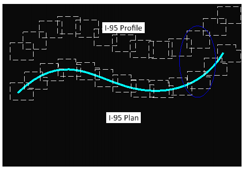
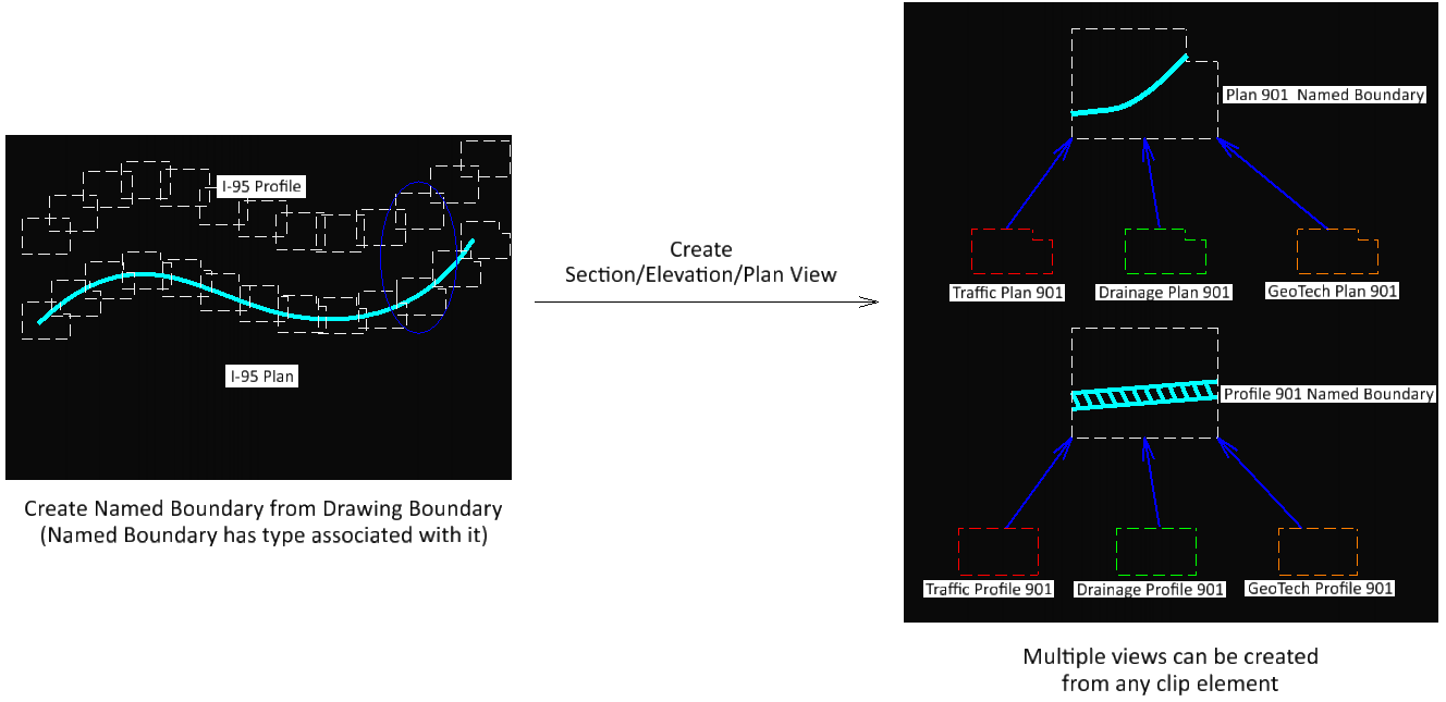
- Select the element (roadway) along which you want to place the named boundaries.
The named boundaries are placed along the roadway.
- In the Create Drawing dialog:
- Select the destination file in the Filename field.
- Select the destination sheet in the selected file from the Sheets drop-down list..
- Select the destination drawing boundary for the plan seed view.
- Click OK.
Each named boundary is referenced on a drawing and sheet model. The selected drawing boundary of the sheet model contains the named boundary.
- Repeat steps 3 and 4 for creating profile named boundaries.