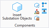
 Used to place objects in the
current model using the symbol name.
Used to place objects in the
current model using the symbol name.
Accessed from:
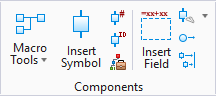
2D Design/Panel
Design
3D Design
Note: If accessing from the 3D ribbon, the Symbol By Part
number will be selected by default. The user will need to switch to the Symbol
By Name mode.
Components Center (Technology Preview) -
Access to catalogs stored in the Components Center has
been added as a technical preview in
OpenUtilities Substation
. The Components Center allows an organization (usually the
project administrator) upload catalog content which can be accessed from any
machine with a user account.
Note: The Component Center will also store the family association of a
symbol to be able to select during the placement process.
Functionality for the Components Center is defined in the
Components Center section of the
Options dialog.

Note: Selecting the
pin button in the upper right corner of the dialog will cause the dialog to
reopen after you finish placing a symbol or macro.
Note: Many of the
panes available in the interface can be moved, docked, minimized, or closed to
suit your preference.
| Setting | Description |
|---|
| Catalog Tree
|
Enables you to navigate to a specific symbol
location. You can filter the list of symbols by selecting a folder in the tree.
|
| Filters Panel
|
- Advanced Filter
Editor - Using this control you can create any number of conditions and combine
them in any manner using any logical operator. Click the + button to add a new
condition. Select the field you want to filter on. Then pick the logical
operator and specify your criteria. You can click the X to clear a filter
condition.
- Apply Filter -
Press this button to apply the filter settings.
|
| Name
|
If you know the name of the symbol that you wish to
place in the drawing, you can enter it in this field. As you enter the name of
the symbol, any existing symbols that match the entered characters will be
listed in the grid.
|
| Symbol List
|
The software lists all the symbols that match any
filters that you have applied. You can apply additional filters by selecting a
field heading and picking the down arrow which displays all the values for that
field. Picking a value will filter the list of symbols and only list those that
have that value.
Clicking on a field heading will sort the list in
ascending order. Clicking a second time will sort it in descending order.
You can click and drag the fields in any order you
wish. Right clicking on any field heading will allow you select which fields
from the database you wish to display. You can toggle on/off fields as desired.
You can select the symbol that you want to place
from the list.
|
| Recently Used Panel
|
Lists the last 10 symbols that you had previously
placed. The list is remembered the next time you restart the software and is
not project specific.
|
| Preview Panel
|
Shows a preview of the symbol for the selected part
number based on the current drawing mode.
|
| Settings Flyout
|
Selecting the down arrow on this button will flyout
the button menu with 3 choices:
- Symbol Settings -
Opens the symbol settings dialog which allows you to specify a rotation angle,
scale factor, and mirror setting which gets applied to any new symbol you
insert.
- Group Settings -
Opens the group settings dialog. If you select more than one item you can place
them as a group. You can make settings to determine how symbols are placed as a
group.
- Reset Dialog - If
you had changed the layout of the dialog from the default or closed any panels
you can reset the dialog to its default layout.
|
| Place Symbol
|
Places a new device, based on the symbol settings
specified.
|
Symbol
Placement
To place the selected symbol in the drawing, click on the
Place Symbol button (or double-click the
symbol name) then position the symbol by pointing the cursor at the desired
location and pressing the left mouse button. The symbol is then placed in the
diagram. The insertion point of the symbol will snap to the nearest grid point.
If the symbol is placed on a wire, the wire will break
automatically at the symbol connection points. If a symbol is placed first and
a wire is drawn over the symbol, the wire will also break automatically.
The symbol will be rotated automatically to match the
horizontal or vertical alignment of a wire. For this to occur, symbol rotation
must be set to 0 degrees and the symbol insertion point must be on the wire.
Also, the Auto Rotate check box must be turned on in symbol settings. Certain
3-phase symbols will not be rotated automatically.
Note: No more than one
wire should be connected to a single symbol connection point.
Once the symbol is placed, the Device Properties dialog
will appear, allowing a device ID, part number and other items to be assigned.
Note: Selecting the pin
button in the upper right corner of the dialog will cause the dialog to reopen
after you finish placing a symbol or macro.
Note: Many of the panes
available in the interface can be moved, docked, minimized, or closed to suit
your preference.
