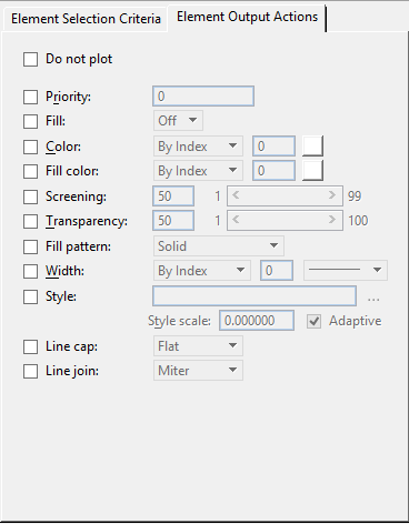
Modify Pen Table Dialog, Element Output Actions Tab
If an element under evaluation matches a section's Element Selection Criteria, then the actions specified using the controls on the Element Output Actions tab (as well as the actions specified in the Text Substitutions dialog) are executed.
- MicroStation BASIC has been replaced with a new standard for recording macros - Bentley Macro Recorder BMR.
- The Bentley Macro Recorder provides a set of features to allow non-programmers to record and play back macros. It also provides elementary level macro editing features.
- All recordings are now stored in BMR format. For experienced VBA programmers, Bentley Macro Recorder provides a way to promote a macro to a VBA.
- The VBA project manager is redesigned and incorporated into the new integrated Macros Management dialog, but the core functionality remains the same.
| Setting | Description |
|---|---|
| Do not plot | When this check box is set, all elements matching the current element section will not be printed. Setting this option also disables all the items on the Output Actions tab. |
| Priority | When this check box is set, you can specify a
priority for all elements matching the current the element section.
An element's priority determines the order in which it is printed in relation to other elements. The valid range of element priorities are (negative) -8000000 to (positive) 8000000. The rules of prioritization are as follows:
To make an element meeting certain criteria print before any other elements, you must prioritize all other elements (those that you do not want printed first) in the entire design. To make elements meeting certain criteria print after other elements, you need only prioritize the elements you wish to be printed last. |
| Fill | Determines whether or not filled areas are printed
for the selected filled elements, such as ellipses, shapes, and complex shapes.
If set, all elements matching the current pen table section will have their
fill states changed to reflect the enabled option button.
|
| Color | If set, lets you control the color of the printed
output for the selected elements. You can select the output color as follows:
|
| Fill Color |
If set, lets you control the color of the printed output of filled areas for the selected elements. You can select the output fill color as follows:
Assigning a fill color does not cause an element that is not already filled to be filled with the specified color. Only elements that are already filled are affected. |
| Screening | If set, you can specify that a color is "washed out" towards white in the printed output. A 50% screen, for example, moves a color halfway to white. Screening can be used to save ink, or to de-emphasize elements plotted in that color. You can choose a value from 1 to 99. |
| Transparency | If set, you can set a value from 1 to 100 to make the selected elements transparent in the printed output. Pen table transparency is supported for any printer driver capable of printing in Rasterized mode. If pen table transparency is used when printing in non-rasterized mode, the transparency values do not have any effect. |
| Fill Pattern | If set, you can choose from one of the following fill patterns: Solid, Checker Board, Cross Hatch, Diamonds, Horizontal Bars, Slant Left, Slant Right, Square Dots, or Vertical Bars. The fill pattern output action is intended to support only AutoCAD plot style tables and therefore the pattern size is fixed. For better control over patterning, use OpenUtilities Substation 's design element hatching and patterning tools. |
| Width | If set, you can define the line weight for the
selected elements in the printed output. Definitions can be either:
|
| Style | If set, you can control the line style and the scale of the selected elements. When this setting is enabled, you can key in the required line style or click the Line style icon to select one from the Select Line Style dialog. When you choose a custom line style, you can use the Style scale control to key in a scale value. To ensure that dashed lines in the printed output do not display with gaps at the vertices, set the Adaptive check box. |
| Line Cap | Used to define the way end caps appear on lines in the printed output. Choices are Flat, Square, Round, or Triangle. |
| Line Join | Used to define the method that line joins appear in the printed output. Choices are Bevel, Miter, Round, or Butt. |