ProStructures differentiates
different dimensioning areas which you can imagine as independent local areas.
The respective alignment is determined by the involved
component parts and influences the indications of place and direction in the
dialogs. As an option, there is also a forced horizontal or vertical alignment
independent of the position for each part dimensioning in a dimensioning area.
Local Areas in
Component Part Groups
Within a view – that means e.g. the front view – these
areas can exist several times except for the global area.
| Setting | Description |
|---|
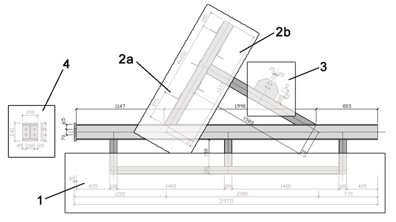
| Global Area (1)
|
These are all dimensioning chains which are
situated outside the component part group and which describe the position of
the sub-parts with regard to the main part. The horizontal alignment is always
determined by the main part of the group and the smallest extent corresponds to
a rectangular which you could draw around all component parts in direction of
the main part.
Since the inner dimensions which are perpendicular
to it are always fixed at the corresponding add-on piece (inner dimensions),
they are assigned to the local area if distances have been specified. The
checked example here shows the area below the group.
|
| Local Area (2a) and Connection Area (2b)
|
These are all dimensioning chains which are
situated inside the component part group and which describe the position of the
sub-parts with regard to their direct reference part.
In case of dimensioning of sub-parts with local
reference (2a), the horizontal alignment is determined by the corresponding
reference part and the smallest extent corresponds to a rectangular around this
reference part.
In case of aligned dimensioning of sub-parts (2b),
the horizontal alignment is determined by the corresponding add-on piece and
the smallest extent corresponds to a rectangular around this add-on piece.
|
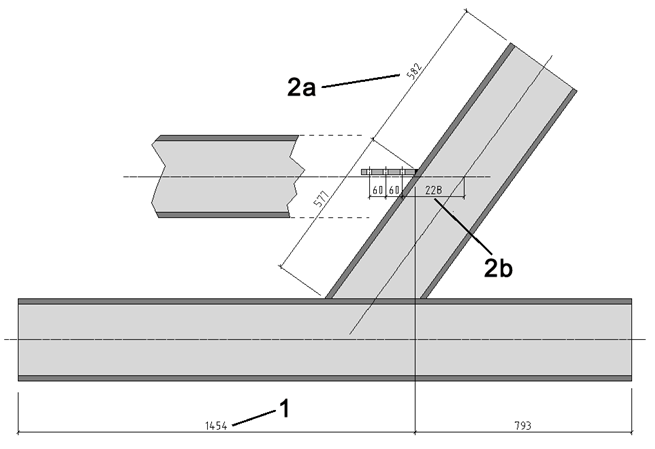
Here, you see a comparison of the three possible variants
by which the butt strap can be dimensioned as an add-on piece of a component
part group. The dimensions according to variant (1) and (2a) are
alternatively possible; the dimensions according to variant (2b) can be
attached in addition.
| Setting | Description |
|---|
| Individual Dimensioning (3)
|
These are all dimensioning chains which are situated
inside the component part group and which describe the production dimensions of
individual sub-parts. The horizontal alignment is determined by the
corresponding subpart and the smallest extent corresponds to a rectangular
around this subpart.
|
| Additional Views (4)
|
These are all dimensioning chains which are
situated outside the component part group in possible additional views so that
here it is strictly speaking a matter of another global area. These additional
views are for example the turned down endplates (here production dimensions) or
cuts and details (here dimensioning of position).
The horizontal alignment is determined by the
alignment of the view and the smallest extent corresponds to a rectangular
which you could draw around all component parts in this view direction.
|
Note: The notion ‘inside’ here refers to a typical setting
of dimensioning distances. At corresponding default settings, these ‘inside’
dimensioning chains can actually be situated outside of the group as well.
If the main part of a component part group or the
local reference parts are bent shapes, the dimensioning direction or the
surrounding rectangular will follow this bend.