STAAD Foundation Advanced Help

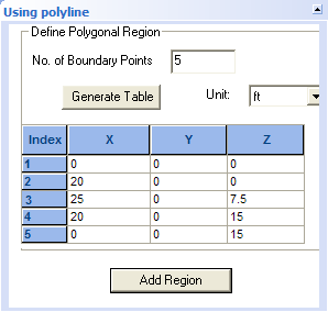
Using Polyline form (Mat Foundation)

Used to create irregularly shaped regions, which can be used to represent slab edges in the Meshing Setup.

Opens when Mat Foundation job > Mesh Generation > Add Meshing Region > Using Polyline is selected.

Note: Polyline regions may be drawn in graphically using the Mat Boundary by Polyline tool, found in the Ribbon toolbar .
SettingDescription
No. of Boundary Points

The number of vertices in the polyline boundary.

Generate Table

Populates the table with a number of rows equal to the No. of Boundary Points specified.

Unit

Select a unit of length for all coordinates in the table.

Polyline coordinates table

Each row represents a polyline vertex. The X,Y, and Z coordinates for each poly line vertex. Note that coordinates should be specified in a clockwise or counterclockwise direction to prevent the polyline from crossing itself (which will in turn produce an error during meshing).

Add Region

Creates a meshing region in the job. The new region will be displayed in a light blue outline in the View window.