AD.2007-07.2.8 AS4100 Physical Member Design
Some of the physical member design updates apply to design codes other than AS 4100, such as checks in the STAAD.Pro analysis engine for physical member overlapping and colinearity. These checks were previously made in the graphical interface but now they will checked again in the engine in the event you have manually generated the STAAD.Pro input file.
The physical member mode is initiated through the Toggle Physical Member mode tool found in the Steel Design toolbar (which docked on the left hand side of the screen by default). This "mode" is used when modeling the structure and any parameter or specification added while this tool is toggled on will then only be available for physical member groups.
Physical members are then formed or selected using the tools in the Steel Design toolbar. Refer to M.フィジカルメンバー for additional information.
Physical Member Restraints
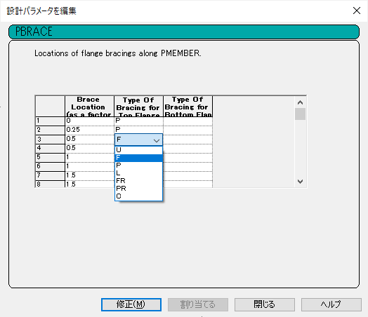
A new parameter has been added for AS 4100 physical members to describe the bracing conditions/locations on a physical member. This parameter describes where the restraint is located along the length of the physical member and the type of restraint on the top or bottom flange.
Engine Physical Member Validation
When creating physical members, the STAAD.Pro graphical interface will check to ensure that the analytical members included in a physical member definition are both interconnected and colinear. However, it is not uncommon for input files to be generated outside of the STAAD.Pro graphical environment. Thus, these checks are now performed by the STAAD.Pro Analysis & Design engine again when an analysis is performed. You will be alerted if either condition is not met.
Refer to D2.B.8 Design Parameters for additional information using the new SGR (steel grade) and LHT (load height position) design parameters for steel design per AS4100. Refer to D2.B.12 Physical Member Design for additional information on using the PBRACE parameter and performing the design of physical members per AS4100.