Next you will assign cross section properties for the
beams and columns.
The STAAD input file commands
generated are:
MEMB PROP
1 4 PRIS YD 300 ZD 275
2 5 PRIS YD 350 ZD 275
3 PRIS YD 350
...
MATERIAL CONCRETE-LTW ALL
-
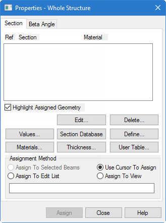
Select the
Properties page in the Analytical Modeling
page control bar.
The
Properties - Whole Structure dialog
opens.
-
Either:
on the
Specifications ribbon tab, click the
Prismatic tool in the
Beam Profiles group

or
click
Define
The
Property dialog opens.
-
Define a 30 cm x 27.5 cm rectangular, concrete beam:
-
Select the
Rectangle tab.
-
Check the
Material option and select
CONCRETE-LTW from the list.
Note: This will
automatically assign the user-defined material created in a previous procedure
to the sections.
-
Type
300 (mm) in the
YD field.
-
Type
275 (mm) in the
ZD field.
-
Click
Add.
-
Repeat step 3 to define the beam member property, this time with a
depth (YD) of
350 and a width (ZD) of
275.
-
Define a 35 cm round, concrete column:
-
Select the
Circle tab.
-
Check the
Material option and select
CONCRETE-LTW from the list.
-
Specify the diameter (YD) as
350 mm.
-
Click
Add.
-
Click
Close.
-
Assign the 30 cm x 27.5 cm shape to members 1 and 4 (end columns):
-
Select
Rect 0.30x0.28 in the list of sections.
-
Select the
Use Cursor to Assign option in the
Assignment Method group.
-
Click
Assign.
The mouse pointer changes to

-
In the view window, click on members 1 and 4.
-
To stop assigning members, either:
click
Assigning
or
press the <Esc> key.
-
Repeat step 7 to assign the 0.35cm x 27.5 cm rectangular shape to
members 2 and 5 (beams).
-
Repeat step 7 to assign the 0.35cm circular shape to members 3
(center column).
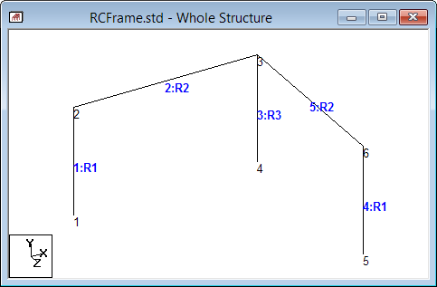
The frame with
sections assigned
Tip: Remember to save your work by either
click
Save on the
File ribbon tab , the
Save tool, or pressing
<CTRL+S>.