TR.26.2 Specifying Constants for Members and Elements
This command may be used to specify the individual material properties (Modulus of Elasticity, Poisson's ratio, Density, Coefficient of linear expansion, and material damping) of the members and elements. In addition, this command may also be used to specify the member orientation (BETA angle or reference point/vector).
General Format
CONSTANTS
To define the orientation:
BETA { f5 | ANGLE | RANGLE } MEMBER memb/elem-list
{ REF f8 f9 f10 | REFJT f11 | REFVECTOR f12 f13 f14 } MEMBER memb/elem-list
To define the material properties:
MATERIAL name { MEMBER member/element-list | (ALL) }
or
{ E f1 | G f2 | POISSON f3 | DENSITY f4 | ALPHA f6 | CDAMP f7 } { MEMBER memb/elem-list | BEAM | PLATE | SOLID | (ALL) }
Where:
- name = material name as specified in the DEFINE MATERIAL command (Refer to TR.26.1 Define Material).
{ REF f8 f9 f10 | REFJT f11 | REFVECTOR f12 f13 f14 } MEMBER memb/elem-list
Where:
- memb/elem-list = MEM, BEA, PLA, SOL, ALL. Only MEM may be followed by a list. If none are specified, the default is to use ALL, which means all members and elements; BEA means all members; PLA, all plates; SOL, all solids.
| Parameter | Value | Description |
|---|---|---|
| E | f1 | Specifies the modulus of elasticity, E (i.e, Young's Modulus). This value must be provided before the POISSON for each member/element in the Constants list. |
| G | f2 | specifies Shear Modulus (G). Enter only for beams when Poisson would not be 0.01 to 0.499. |
| POISSON | f3 | specifies Poisson's Ratio, υ. This value is used for calculating the Shear Modulus (G = 0.5xE/(1+υ)). |
| DENSITY | f4 | specifies weight per unit volume, γ |
| ALPHA | f6 | Coefficient of thermal expansion, a |
| CDAMP | f7 | Damping ratio to be used in computing the modal damping by the composite damping method in a dynamic analysis when CDAMP has been specified. Damping must be in the range of 0.001 to 0.990. |
| BETA | f5 | Specifies member rotation angle in degrees (Refer to G.4.3 Relationship Between Global and Local Coordinates). |
The following values are used in various methods to define the BETA angle based on geometry:
- f8, f9, f10 = Global X, Y, and Z coordinates for the reference point
- f11= use location of joint f11 for the reference point, from which the BETA angle will be calculated by STAAD.Pro.
- f12, f13, f14 = Establishes a Reference Vector along which the local y-axis is aligned. From the start node of the member, move by a distance of f12 along the beam's local X axis, f13 along the local Y axis, and f14 along the local Z axis to define the end node of the reference vector. (The BETA angle is thus the angel between the local y-axis and the reference vector)
Using BETA ANGLE and RANGLE
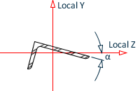
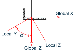
Single angle sections are oriented according to their principal axes by default. If it is necessary to orient them such that their legs are parallel to the global axes, the BETA specification must be used. STAAD.Pro offers the following additional specifications for this purpose:
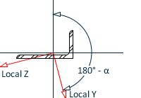
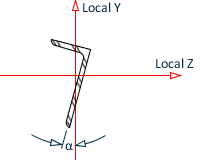
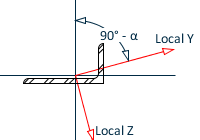
Both of the above options will result in an orientation with the legs parallel to the global axis. The ANGLE option rotates the section counterclockwise by the angle, α (where α = angle between the principal axis system and the geometric axis system of the angle). The RANGLE option rotates the section counterclockwise by an angle equal to (180° - α). For unequal angles, the right option must be used based on the required orientation.
| BETA value = | Zero (0) | ANGLE | RANGLE |
|---|---|---|---|
| ST Angle |
|

|
|
| RA Angle |
|
|

|

Orientation of an angle profile vertically aligned (i.e,. local x = Global Y) with (A) BETA = 0 (default) and (B) BETA = ANGLE
Built-In Material Constants
For E, G, POISSON, DENSITY, ALPHA, and CDAMP, built-in material names can be entered instead of a value for f1. The built-in names are STEEL, CONCRETE, & ALUMINUM. Appropriate values will be automatically assigned for the built-in names.
| Constant | Material | Units | ||
|---|---|---|---|---|
| Steel | Concrete | Aluminum | ||
| E (US) | 29,000 | 3,150 | 10,000 | Kip/in2 |
| Poisson’s | 0.30 | .17 | .33 | (ratio) |
| Density | .000283 | .0000868 | .000098 | Kip/in3 |
| Alpha | 6.5E-6 | 5.5E-6 | 12.8E-6 | L/L/° F |
| CDAMP | .03 | .05 | .03 | (ratio) |
| E (nonUS) | 29,732.736 | Kip/in2 | ||
| Constant | Material | Units | ||
|---|---|---|---|---|
| Steel | Concrete | Aluminum | ||
| E (US) | 199, 947,960 | 21,718,455 | 68,947,573 | kN/m2 |
| Poisson’s | 0.30 | .17 | .33 | (ratio) |
| Density | 76.819 541 | 23.561612 | 26.601820 | kN/m3 |
| Alpha | 12.0E-6 | 10.0E-6 | 23.0E-6 | L/L/° C |
| CDAMP | .03 | .05 | .03 | (ratio) |
| E (nonUS) | 205, 000,000 | kN/m2 | ||
Example 1
DEFINE MATERIAL
ISOTROPIC CFSTEEL
E 28000.
POISSON 0.25
DENSITY 0.3E-3
ALPHA 11.7E-6
DAMP 0.075
END MATERIAL
CONSTANTS
MATERIAL  CFSTEEL MEMB 1 TO 5
CONSTANTS
E 2.1E5  ALL
BETA 45.0  MEMB  5  7  TO  18
DENSITY STEEL MEMB  14  TO  29
BETA  90  MEMB X
Example 2
The REFVECTOR command is used as in the following example:
REFVECTOR 0 2 1 MEMBER 27 TO 32
This command will set BETA as 90° for all members parallel to the X-axis and instructs the program to do the following procedure:
-
Establish the beam's local X,Y and Z axis corresponding to Beta = 0
-
Set the start node of the reference vector to be the same as the start node of the member.
-
From the start node of the reference vector, move by a distance of 0 along the beam's local X axis, 2 along the local Y axis, and 1 along the local Z axis. This establishes the end node of the reference vector.
-
At the end of step 3, the start node as well as the end node of the reference vector are known. That is the now the final direction of the member's local Y axis.
Since the local Y axis corresponding to Beta 0 is known, and the local-Y axis corresponding to the beam's final position has been established in step 4, Beta angle is calculated as the angle between these two vectors.
In this example, the angle is Tan-1(1/2) = 26.5651 degrees
Notes
-
The value for E must always be given first in the Constants list for each member/element.
-
All numerical values must be provided in the current units.
-
It is not necessary or possible to specify the units of temperature or ALPHA. You must ensure that the value provided for ALPHA is consistent in terms of units with the value provided for temperature (see TR.32.6 Temperature Load Specification for Members, Plates, and Solids).
-
If G is not specified, but Poisson (υ) is specified, G is calculated as E/[2 (1+υ)].
-
If neither G nor Poisson is specified, Poisson is assumed based on E, and G is then calculated.
-
If G and Poisson are both specified, the input value of G is used. That is, G is not calculated in this situation.
-
If G and Poisson are both required in the analysis, such as for the stiffness matrix of plate elements, and G is specified, but Poisson is not, then, Poisson is calculated as [(E/2G) –1].
-
To obtain a report of the values of these terms used in the analysis, specify the command PRINT MATERIAL PROPERTIES.
-
Local offsets are defined in the local axes prior to rotation when a BETA angle is used.