D1.B.1.2 Design Parameters
The program contains a large number of parameter names which are needed to perform designing and code checking. These parameter names, with their default values, are listed in the following table. These parameters communicate design decisions from the engineer to the program.
The default parameter values have been selected such that they are frequently used numbers for conventional design. Depending on the particular design requirements of an analysis, some or all of these parameter values may have to be changed to exactly model the physical structure. For example, by default the KZ (k value in local z-axis) value of a member is set to 1.0, while in the real structure it may be 1.5. In that case, the KZ value in the program can be changed to 1.5, as shown in the input instructions. Similarly, the TRACK value of a member is set to 0.0, which means no allowable stresses of the member will be printed. If the allowable stresses are to be printed, the TRACK value must be set to 1.0.
The parameters PROFILE, DMAX, and DMIN are only used for member selection.
| Parameter Name | Default Value | Description |
|---|---|---|
| AXIS | 1 |
Select axis about which single angles are design
|
| BEAM | 1.0 |
Used to specify the number of sections at which the member design is evaluated.
|
| BMAX | 83.3333 ft | Maximum allowable width of the flange. Used in the design of tapered sections. |
| CAN | 0 |
Specifies the method used for deflection checks
|
| CB | 1.0 | Cb value as used in Section 1.5 of AISC. Use 0.0 to direct the program to calculated Cb. Any other value be used in lieu of the program calculated value. |
| CDIA | 0.0 | The diameter of circular openings. If a member has more than one circular opening, they can have different diameters. |
| CHOLE | NONE | Section locations of circular openings along the length of the member. Maximum three locations can be specified for each member when there is no rectangular opening. |
| CMP | 0 |
Composite action with connectors
|
| CMZ | 0.85 for sidesway and calculated for no sidesway | Cm value in local y and z axes, respectively. |
| CYC | 500,000 | Cycles of maximum stress to which the shear connectors are subject. |
| DFF | none (mandatory for deflection check) | "Deflection Length" / Maximum allowable local deflection |
| DIA | 0.625 in. | Diameter of the shear connectors |
| DINC | 1 in | Incremental depth value used in the design of tapered sections. |
| DJ1 | Start Joint of member | Joint No. denoting starting point for calculation of "Deflection Length" (see note 1) |
| DJ2 | End Joint of member | Joint No. denoting end point for calculation of "Deflection Length" (see note 1) |
| DMAX | 1000 in. | Maximum allowable section depth. |
| DMIN | 0.0 in. | Minimum allowable section depth. |
| DR1 | 0.4 | Ratio of moment due to dead load applied before concrete hardens to total moment. |
| DR2 | 0.4 | Ratio of moment due to dead load applied after concrete hardens to total moment. |
| ELECTRODE | 1 |
Weld material to be used for reinforced opening.
|
| FBINC | 0 | Incremental bottom flange width used in the design of tapered sections. In this case, the top flange width will remain unchanged. |
| FLX | 1 |
Single angle member bracing
|
| FPC | 3.0 ksi | Compressive strength of concrete at 28 days |
| FSS | 1 |
Is the full section to be used for shear design?
|
| FTBINC | 0 | Incremental flange width (top and bottom) used in the design of tapered sections. |
| FTINC | 0 | Incremental top flange width used in the design of tapered sections. In this case, the bottom flange width will remain unchanged. |
| FU | Depends on FYLD |
Ultimate tensile strength of steel in current units.
|
| FYLD | 36 KSI | Yield strength of steel in current units. |
| HECC | 0.0 | Eccentricity of opening with respect to the centerline of the member. |
| KX | 1.0 | K value used in computing KL/r for flexural torsional buckling for tees and double angles. |
| KY | 1.0 |
Effective length factor to calculate slenderness ratio for buckling about local y-axis. Usually this is the minor axis. |
| KZ | 1.0 |
Effective length factor to calculate slenderness ratio for buckling about local z-axis. Usually this is the major axis. |
| LX | Member Length | Length value used in computing KL/r for flexural torsional buckling for tees and double angles. |
| LY | Member Length | Length used to calculate slenderness ratio for buckling about the local y-axis. |
| LZ | Member Length | Same as LY, but in the local z-axis. |
| MAIN | 0.0 |
Toggles the slenderness check
Any value greater than 1 = Allowable KL/r in compression. |
| NSF | 1.0 | Net section factor for tension members. |
| OVR | 1.0 | Overstress factor. All the allowable stress are multiplied by this number. It may be assigned any value greater than 0.0. It is used to communicate increases in allowable stress for loads like wind and earthquake. |
| PLTHICK | 0.0 | Thickness of cover plate welded to the bottom flange of the composite beam. |
| PLWIDTH | 0.0 | Width of cover plate welded to the bottom flange of the composite beam. |
| PROFILE | Used in member selection. Refer to TR.48.1 Parameter Specifications for details. | |
| RATIO | 1.0 | Permissible ratio of actual to allowable stress. |
| RDIM | 0.0 | Dimensions of rectangular openings (at each section, RDIM has a length term and a depth term – see syntax below). If a member has more than one rectangular opening they can have different dimensions. |
| RHOLE | None | Section locations of rectangular openings along the length of the member. Maximum three locations can be specified for each member when there is no circular opening. |
| RBHEIGHT | 0.0 | Height of ribs in the form steel deck. |
| RBWIDTH | 2.5 in. | Width of ribs in the form steel deck. |
| SHE | 0 |
Option for calculating actual shear stress.
|
| SHR | 0 |
Indicates use of temporary shoring during construction.
|
| SSY | 0.0 |
Sidesway
|
| SSZ | 0.0 | Same as SSY, but in local z-axis. |
| STIFF | Member Length or depth of beam, whichever is greater | Spacing of stiffeners for plate girder design. |
| STP | 1 |
Section type as defined in ASD Manual table.
|
| TAPER | 1.0 |
Design basis for tapered members
|
| THK | 4.0 in. | Thickness of concrete slab or the thickness of concrete slab above the form steel deck. |
| TMAIN | 300 | Any value greater than 1 = Allowable KL/r in tension. |
| TORSION | 0.0 |
Toggles the check for torsion
|
| TRACK | 0.0 |
Controls the level of detail to which results are reported:
|
| UNB | Member Length | Unsupported length of the bottom* flange for calculating allowable bending compressive stress. Will be used only if flexural compression is on the bottom flange |
| UNT | Member Length | Unsupported length of the top* flange for calculating allowable bending compressive stress. Will be used only if flexural compression is on the top flange. |
| WELD | 1 for closed sections, 2 for open sections |
Weld type as described in D1.B.1.10 Weld Design:
|
| WIDTH | 0.25 times the member length | Effective width of the concrete slab. |
| WMAX | Maximum welding thickness. | |
| WMIN | Minimum welding thickness. | |
| WSTR | 0.4 × FYLD | Allowable weld stress. Refer to D1.B.1.10 Weld Design for how WELD, WMAX, WMIN, and WSTR parameters are used in weld design. |
*Top and Bottom represent the positive and negative side of the local Y axis (local Z axis if SET Z UP is used).
Notes
-
When performing the deflection check, you can choose between two methods. The first method, defined by a value 0 for the CAN parameter, is based on the local displacement. See TR.44 Printing Section Displacements for Members for details on local displacement.
If the CAN parameter is set to 1, the check will be based on cantilever style deflection. Let (DX1, DY1,DZ1) represent the nodal displacements (in global axes) at the node defined by DJ1 (or in the absence of DJ1, the start node of the member). Similarly, (DX2, DY2, DZ2) represent the deflection values at DJ2 or the end node of the member.
Compute Delta =
Compute Length = distance between DJ1 and DJ2 or, between start node and end node, as the case may be.
Then, if CAN is specified a value 1, dff = L/Delta
Ratio due to deflection = DFF/dff
-
If CAN = 0, deflection length is defined as the length that is used for calculation of local deflections within a member. It may be noted that for most cases the "Deflection Length" will be equal to the length of the member. However, in some situations, the "Deflection Length" may be different.
For example, refer to the figure below where a beam has been modeled using four joints and three members. The "Deflection Length" for all three members will be equal to the total length of the beam in this case. The parameters DJ1 and DJ2 should be used to model this situation. Also the straight line joining DJ1 and DJ2 is used as the reference line from which local deflections are measured. Thus, for all three members here, DJ1 should be "1" and DJ2 should be "4".
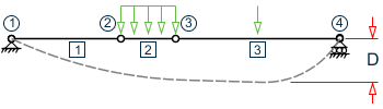
D is equal to the maximum local deflection for members 1, 2, and 3.
PARAMETERS
DFF 300. ALL
DJ1 1 ALL
DJ2 4 ALL
-
If DJ1 and DJ2 are not used, "Deflection Length" will default to the member length and local deflections will be measured from original member line.
-
It is important to note that unless a DFF value is specified, STAAD.Pro will not perform a deflection check. This is in accordance with the fact that there is no default value for DFF.
-
A critical difference exists between the parameters UNT/UNB and the parameters LY and LZ. Parameters UNT and UNB represent the laterally unsupported length of the compression flange. It is defined in Chapter F, page 5-47 of the specifications in the AISC 1989 ASD manual as the distance between cross sections braced against twist or lateral displacement of the compression flange. These parameters are used to calculate the allowable compressive stress (FCZ and FCY) for behavior as a beam. Parameters LY and LZ are the unbraced lengths for behavior as a column and are used to calculate the KL/r ratios and the allowable axial compressive stress FA.
-
Parameters SSY and CMY are based upon two values defined in page 5-55, Chapter H of the AISC 9th ed. manual. SSY is a variable which allows you to define whether or not the member is subject to sidesway in the local Y direction. CMY is a variable used for defining the expression called Cm in the AISC manual. When SSY is set to 0 (which is the default value), it means that the member is subject to sidesway in the local Y direction. When SSY is set to 1.0, it means that the member is not subject to sidesway in the local Y direction. The only effect that SSY has is that it causes the program to calculate the appropriate value of CMY. If SSY is set to 0 and CMY is not provided, STAAD.Pro will assume CMY as 0.85. If SSY is set to 1 and CMY is not provided, STAAD.Pro will calculate CMY from the equation on page 5-55. However, if you provide CMY, the program will use that value and not calculate CMY at all, regardless of what you defines SSY to be.
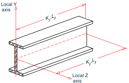
Terms used in calculating slenderness ratios KL/r for local Y and Z axes
-
For a T shape which is cut from a parent I, W, S, M or H shapes, the PROFILE parameter should be assigned a value corresponding to the parent shape. For example, if the T desired is an American WT6, specify W12 for the PROFILE parameter.