T.1 Specifying member offsets
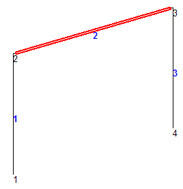
Member 2 (the beam) actually spans only the clear distance between the column faces rather than the center to center distance. This is modeled by specifying offsets.
Member 2 is offset at the start joint by 6 inches in the global X direction (and 0.0 and 0.0 in Y and Z directions). The same member is offset by negative 6.0 inches at its end joint.
The STAAD input file commands generated are:
MEMBER OFFSET
2 START 6.0 0.0 0.0
2 END -6.0 0.0 0.0- Select member 2 by clicking on it in the view window.
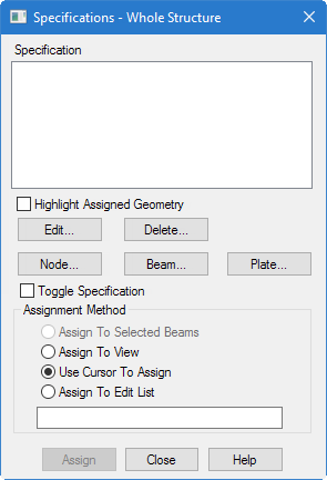
- Select the Specifications page on the Analytical Modeling page bar. The Specifications - Whole Structure dialog opens. Member releases, offsets, and other beam specifications are defined here.
- Click Beam.
-
Specify the member start offset:
- Select the Offset tab.
- Select Start as the Location.
-
Type
6.0(in.) in the
X offset field.
Leave the Direction as Global. It is convenient to define the offset at the start node in the X direction. Since the beam member is aligned with the global X axis, there is no difference between choosing a global or local frame of reference.
- Click Assign.
-
On the
Specification ribbon tab, select the
tool in the
Specifications group.

The Member Specification dialog opens to the Offsets tab.
- Specify the member end offset: The dialog closes and the offset specification is added to the start of member 2.