Define Input tab
Used to define general definition and member specific parameters for a pushover analysis.
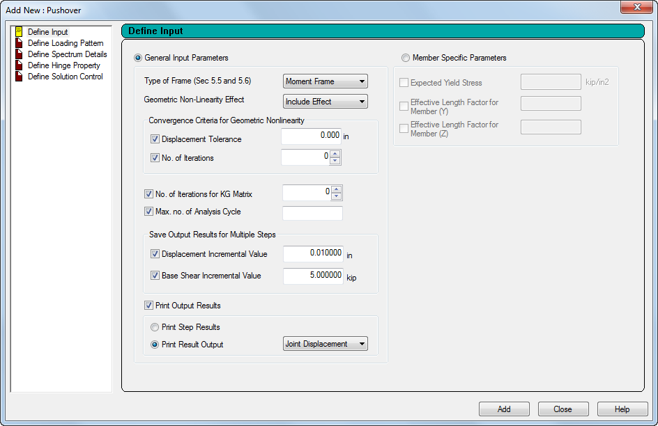
General Input Parameters
Select this control to add general parameters for the entire structure.
| Setting | Description |
|---|---|
| Type of Frame |
Select either a fully restrained Moment Frame (FR) or a (Concentric) Braced Frame (CBF) to defined the type of steel frame. |
| Geometric Non-Linearity Effect |
Select either Ignore Effect, if nonlinear effects are not to be considered, or Include Effect, if nonlinear effects are to be considered. |
| Displacement Tolerance |
(For when Geometric Non-Linearity Effect is considered only) Set this option to specify a displacement tolerance for convergence, in current input units. |
| No. of Iterations |
(For when Geometric Non-Linearity Effect is considered only) Set this option to specify a target number of iterations for geometric nonlinearity convergence. |
| No. of Iterations for KG Matrix |
Set this option to specify the number of iterations to be performed for geometric stiffness, KG, matrix. The value is a integer, with a maximum value of 50. |
| Max. no. of Analysis Cycles |
Set this option to specify a maximum number of cycles to be considered during the strain hardening stage for the load increment stage. |
| Displacement Incremental Value |
Set this option to include intermediate displacement increments, in current units of length, at which the program will record analysis results for post-processing. |
| Base Shear Incremental Value |
Set this option to include intermediate base shear increments, in current units of force, at which the program will record analysis results for post-processing. |
| Print Output Results |
Set this option to print analysis results for the final state for a nonlinear static analysis.
|
Member Specific Parameters
Select this control to add parameters for members which will be assigned later.
| Setting | Description |
|---|---|
| Expected Yield Stress |
Expected yield strength of the material based on Section 5.3.2.3 and Tables 5-1 and 5-2 of FEMA 356. |
| Effective Length Factor for Member (Y/Z) |
The effective length factor, k, defined for any member in either the local Y or local Z direction. |