D8.B.12 Built-in Indian Steel Table
This is an important feature of the program since the program will read section properties of a steel member directly from the ISI steel tables (as published in ISI-800). These properties are stored in memory corresponding to the section designation (e.g., ISMB250, etc.). If called for, the properties are also used for member design. Since the shear areas are built in to these tables, shear deformation is always considered for these members.
Almost all ISI steel tables are available for input. A complete listing of the sections available in the built-in steel section library may be obtained using the tools of the graphical user interface.
D8.B.12.1 Rolled Steel Beams (ISJB, ISLB, ISMB, and ISHB)
All rolled steel beam sections are available the way they are designated in the ISI handbook (e.g., ISJB225, ISWB400, etc.)
20 TO 30 TABLE ST ISLB325
1 TO 5 TABLE ST ISHB400A
D8.B.12.2 Rolled Steel Channels (ISJC, ISLC and ISMC)
All these shapes are available as listed in ISI section handbook. Designation of the channels are per the scheme used by ISI.
10 TO 20 BY 2 TABLE ST ISMC125
12 TABLE ST ISLC300
D8.B.12.3 Double Channels
Back to back double channels, with or without spacing between them, are available. The letter D in front of the section name will specify a double channel (e.g., D ISJC125, D ISMC75, etc.).
21 22 24 TABLE D ISLC225
D8.B.12.4 Rolled Steel Angles
Both rolled steel equal angles and unequal angles are available for use in the STAAD implementation of ISI steel tables. The following example with explanations will be helpful in understanding the input procedure:
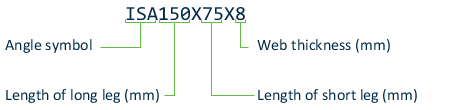
At present there is no standard way to define the local y and z axes for an angle section. The standard section has local axis system. The standard angle is specified as:
51 52 53 TABLE ST ISA60X60X6
This specification has the local z-axis (i.e., the minor axis corresponding to the V-V axis specified in the steel tables. Many engineers are familiar with a convention used by some other programs in which the local y-axis is the minor axis. STAAD.Pro provides for this convention by accepting the command:
54 55 56 TABLE RA ISA50X30X6
D8.B.12.5 Double Angles
Short leg back-to-back or long leg back-to-back double angles can be specified by inputting the word SD or LD, respectively, in front of the angle size. In case of an equal angle either LD or SD will serve the purpose. For example,
14 TO 20 TABLE LD ISA50X30X5 SP 1.5
23 27 TABLE SD ISA75X50X6
D8.B.12.6 Rolled Tees (ISHT, ISST, ISLT and ISJT)
All the rolled tee sections are available for input as they are specified in the ISI handbook. The following example illustrates the designated method.
1 2 5 8 TABLE ST ISNT100
67 68 TABLE ST ISST250
D8.B.12.7 Pipes (Circular Hollow Sections)
To designate circular hollow sections from ISI tables, use PIP followed by the numerical value of diameter and thickness of the section in mm omitting the decimal section of the value provided for diameter. The following example will illustrate the designation.
10 15 TABLE ST PIP 213.2
specifies a 213 mm dia. pipe with 3.2 mm wall thickness
Circular pipe sections can also be specified by providing the outside and inside diameters of the section. For example,
1 TO 9 TABLE ST PIPE OD 25.0ID 20.0
specifies a pipe with outside dia. of 25 and inside dia. of 20 in current length units
Only code checking and no member selection will be performed if this type of specification is used.
D8.B.12.8 Tubes (Rectangular or Square Hollow Sections)
Designation of tubes from the ISI steel table is illustrated below.

For example,
15 TO 25 TABLE ST TUB 160808
Tubes, like pipes, can also be input by their dimensions (Height, Width and Thickness) and not by any table designations.
6 TABLE ST TUBE DT 8.0 WT 6.0 TH 0.5
is a tube that has a height of 8, a width of 6, and a wall thickness of 0.5.
D8.B.12.9 Plate And Angle Girders (With Flange Plates)
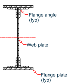
Plate and Angle girder
Plate and angle grinders (with flange plates) are available as listed in Table XX of the ISI section handbook. The input of these composite sections are given as indicated in the following diagram. The web height and thickness are the first numeric entries, followed by a letter identifier used to indicate the angle size used, the followed by the flange width and thickness entries.

Flange angle key
| Angle Identifier | Angle Size Used (A × B × t) |
|---|---|
| A | 150×150×18 |
| B | 200×100×15 |
| C | 200×150×18 |
| D | 200×200×18 |
D8.B.12.10 Single Joist with Channels and Plates on the Flanges to be Used as Girders
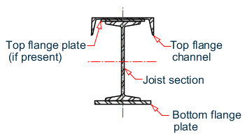
Single Joist with Channel and Plates on the Flanges
All single joist with channel and plates on the flanges to be used as girders are available as listed in Table XV of the ISI section handbook. The input of these composite sections are given as indicated in the following diagram. The following example with explanations will be helpful in understanding the input procedure.
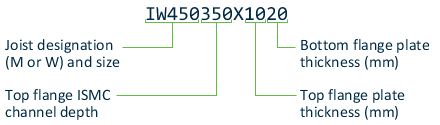
The plate widths are specific to the combination of joist and channel, so they are not directly specified in the section size. To specify a section without a top flange plate (to flange channel only), then a zero may be specified for the top flange thickness value. For example, a IM600400X016 indicates an ISMB 600 joist with an ISMC 400 top flange channel (no plate) and a 320×16 mm bottom plate.