V.API Overlapping KJoint - Comp and Bend
Verify the design of an overlapping K joint with axial load, in-plane bending, and out-of-plane bending.
Details
Design of node 3 in the following model.
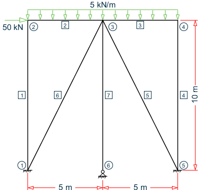
Chord member (2 & 3): D = 500 mm, T = 20 mm (Ac = 30,159 mm2, Zc = 3,480,380 mm3)
Brace member (5 & 7): d = 400 mm, t = 20 mm (Ab = 23,876 mm2, Zb = 2,160,790 mm3)
Validation
Design Parameters
β = d/D = 0.8
So, 0.2 < β < 1.0 (OK)
γ = D/2T = 12.5
So, 10 < γ < 50 (OK)
θ = tan-1(10/5) = 63.4°
So, 30° < θ < 90° (OK)
Fy = 500 MPa (OK)
g = -76.2 mm
g/D = -76.2 / 500 = -0.1524
Determination of Qu
First, evaluate Qg. Since g/D < -0.50, use linear interpolation.
For g/D = -0.05: Qg = 0.13 + 0.65×ϕ×γ0.5 = 0.13 + 0.65×(1)×(12.5)0.5 = 2.428
Qu_ax = (16 + 1.2×γ)×β1.2×Qg = [16 + 1.2(12.5)](0.8)1.2(2.428) = 57.586
Qu_ipb = (5 + 0.7×γ)×β1.2 = [5 + 0.7(12.5)](0.8)1.2 = 10.52
Qu_opb = 2.5 + (4.5 + 0.2×γ)×β2.6 = 2.5 + [4.5 + 0.2(12.5)](0.8)2.6 = 6.419
Determination of Qf
From Table 4.3.2:
C1ax = 0.2, C2axi = 0.2, C3ax = 0.3
C1ipb = 0.2, C2ipb = 0, C3ipb = 0.4
C1opb = 0.2, C2opb = 0, C3opb = 0.4
Pyc = Ac×Fyc = 15,079.5 kN
Mpc = Zc×Fyc = 1,740.19 kN·m
Pc = 49.99 KN
Mc = √ (MIPC2+MOPC2) = 18.267 kN·m
Axial Capacity
Moment Capacity
In-plane bending:
Out-of-plane bending:
Brace Loads
As axial loads for through and overlapping brace are of different sign, resultant axial load will be that of through brace. (Page 65, API code).
Axial load = 72.511 kN (C)
According to Page 65 of the API code, the resultant in-plane and out-plane bending moments will be algebraic summation of moments of the through brace and overlapping brace.
In-plane moment = 0.727 + (-0.89) = -0.163 kN·m
Out-of-plane moment = 6.254 + 6.254 = 12.508 kN·m
Interaction Ratio
P/Pa + (M/Ma)ip2+ (M/Ma)op = (72.511 / 8,014.5) + (0.163 / 588.85)2 + (12.508 / 359.31) = 0.044
Results
| Result Type | Reference | STAAD.Pro | Difference | Comments |
|---|---|---|---|---|
| Qu_ax | 57.586 | 57.617 | negligible | |
| Qu_ipb | 10.52 | 10.523 | negligible | |
| Qu_opb | 6.419 | 6.419 | none | |
| Qf_ax | 0.9989 | 0.999 | negligible | |
| Qf_ipb | 1.001 | 1.001 | none | |
| Qf_opb | 1.001 | 1.001 | none | |
| Axial capacity (kN) | 8,041.5 | 8,029.9 | negligible | |
| In-plane Bending Capacity (kN·m) | 588.86 | 588.1 | negligible | |
| Out-of-plane Bending Capacity (kN·m) | 359.31 | 358.74 | negligible | |
| Interaction ratio | 0.044 | 0.044 | none |
STAAD.Pro Input File
The file C:\Users\Public\Public Documents\STAAD.Pro 2023\Samples \Verification Models\09 Steel Design\US\API\API Overlapping KJoint - Comp and Bend.std is typically installed with the program.
STAAD SPACE
START JOB INFORMATION
ENGINEER DATE 12-Mar-19
END JOB INFORMATION
INPUT WIDTH 79
UNIT METER KN
JOINT COORDINATES
1 0 0 0; 2 0 10 0; 3 5 10 0; 4 10 10 0; 5 10 0 0; 6 5 0 0;
MEMBER INCIDENCES
1 1 2; 2 2 3; 3 3 4; 4 4 5; 5 3 5; 6 3 1; 7 3 6;
DEFINE MATERIAL START
ISOTROPIC STEEL
E 2.05e+008
POISSON 0.3
DENSITY 76.8195
ALPHA 1.2e-005
DAMP 0.03
TYPE STEEL
STRENGTH FY 253200 FU 407800 RY 1.5 RT 1.2
END DEFINE MATERIAL
MEMBER PROPERTY AMERICAN
1 4 7 TABLE ST W6X12
5 6 TABLE ST PIPE OD 0.4 ID 0.36
2 3 TABLE ST PIPE OD 0.5 ID 0.46
CONSTANTS
MATERIAL STEEL ALL
SUPPORTS
1 5 FIXED
6 PINNED
LOAD 1 LOADTYPE Dead  TITLE LOAD CASE 1
JOINT LOAD
2 FX -50
MEMBER LOAD
2 3 UNI GY -5
2 3 CMOM Y 5
PERFORM ANALYSIS
PRINT MEMBER PROPERTIES ALL
PARAMETER 1
CODE API
*FSJ 2.6 ALL
FYLD 500000 ALL
TRACK 2 ALL
CHECK CODE ALL
FINISH
STAAD.Pro Output
======================================================================
NODE NO :      3   CHORD NO:     2   BRACE NO:     6
======================================================================
DESIGN DATA : (Units    : N , mm  )
  Chord Memb :      D =  500.00  T = 19.99
  Brace Memb :      d =  400.00  t = 19.99
  Angle (THETA) =  63.4 deg  GAP   =  -76.20   Fyc = 499.9
  BETA          =  0.80      GAMMA =   12.51   TAU =  1.00
      STAAD SPACE                                              -- PAGE NO.    7
      ***WARNING - JNT      3: OVERLAP
      OVERLAP PROVIDED =  76.20 IS LESS THAN THE NOMINAL VALUE OF 0.25*BETA*D.
JOINT CLASS :          KO
  Overlap Brace :       5   Angle =   63.43 deg.   Diam. =  400.00
  FACTORS :
  --------------------------------------------------------------------
  Joint   Load   Strength     Chord Load    C1        C2        C3
  Class   Cond   factor (Qu)  factor (Qf)
  --------------------------------------------------------------------
    K     AX      57.617        0.999       0.200    0.200    0.300
    K     IPB     10.523        1.001       0.200    0.000    0.400
    K     OPB      6.419        1.001       0.200    0.000    0.400
----------------------------------------------------------------------
CAPACITY CHECKS        BRACE LOAD    LC   CAPACITY   RATIO   STATUS
   (Cl. 4.3)             (KN, m )         (KN, m )
----------------------------------------------------------------------
AXIAL        :            -72.51      1     8029.90    0.009   PASS
IP BENDING   :             -0.16      1      588.09    0.000   PASS
OP BENDING   :             12.51      1      358.74    0.035   PASS
INTERACTION  :                        1                0.044   PASS
----------------------------------------------------------------------
CRITICAL     :                        1                0.044   PASS
----------------------------------------------------------------------