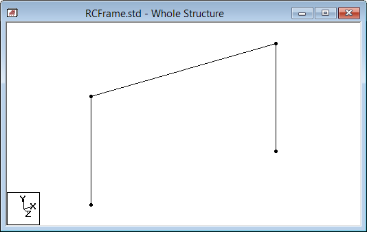
T.2 Generating the model geometry
The structure geometry consists of joint numbers, their coordinates, member numbers, the member connectivity information, plate element numbers, etc.
The STAAD input file commands generated are:
JOINT COORDINATES
1 0.0 0.0 0.0 ; 2 0.0 3.5 0.0
3 6.0 3.5 0.0 ; 4 6.0 0.0 0.0
5 6.0 0.0 6.0 ; 6 6.0 3.5 6.0
MEMBER INCIDENCE
1 1 2 ; 2 2 3 ; 3 3 4 ; 4 5 6 ; 5 3 6
 in the
-
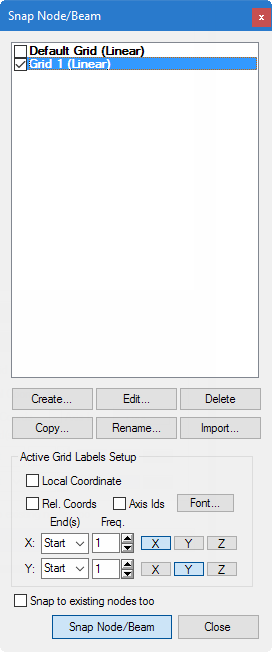
On the
Snap Node/Beam dialog, click
Create.
A dialog
opens which will enable us to set up a grid.
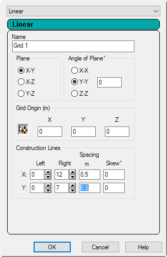
Within this dialog, there is a drop-down list from which you can select Linear, Radial, or Irregular form of grid lines.
Setting Description Linear used to place the construction lines perpendicular to one another along a "left to right - top to bottom" pattern, as in the lines of a chess board Radial used to place construction lines to appear in a spider-web style, which makes it is easy to create circular type models where members are modeled as piece-wise linear straight line segments Irregular used to create gridlines with unequal spacing that lie on the global planes or on an inclined plane -
Select
Linear,which is the Default Grid.
In this structure, the portion consisting of members 1 to 3, and nodes 1 to 4, happens to lie in the X-Y plane. Leave X-Y as the Plane of the grid. The size of the model that can be drawn at any time is controlled by the number of Construction Lines to the left and right of the origin of axes, and the Spacing between adjacent construction lines.
- Type a Name of Grid 1.
- Type 12 as the number of lines to the Right of the origin along X and 7 above the origin along Y.
- Type a Spacing of 0.5 m between lines along both XandY (see figure below) we can draw a frame 6m X 3.5m, adequate for our segment.
- Click OK.
-
In the
Snap Node/Beam grids list, check
the new
Grid 1 option.
You can create any number of grids. By providing a name, each new grid can be identified for future reference.
Tip: Please note that these settings are only used to generated construction lines. These construction lines enable you to easily draw the structure but do not restrict our overall model to those limits.Tip: To change the settings of this grid, select the name in the Snap Node/Beam dialog and then click Edit.The check by Default Grid is automatically cleared. STAAD.Pro will only display a single grid at a time.
-
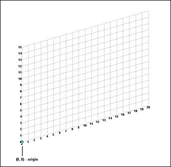
In the View window, click at the origin (0, 0) to create the first
node.
A line is "rubber-banded" between this node and the mouse pointer, which previews the member to placed with the next mouse click.
-
Click on the following points to create nodes and automatically
join successive nodes by beam members.
- (0, 3.5)
- (6, 3.5)
- (6, 0)
- Click Close in the Snap Node/Beam dialog. The grid is hidden.