D12.A.4 Stability Check According to NS 3472
The stability check is based on the assumption that both ends of the member are structural nodes. Buckling lengths and results for member with joints between the structural nodes have to be evaluated in each separate case.
Effects from local buckling or external hydrostatic pressure on pipes and tubes are not included.
The general stability criteria is: (ref. NS 12.3)
D12.A.4.2 Lateral Buckling
Where:
i = z,y
nmax = n/χmin
n = Nf/Nd
χmin = min(χz,χy)
χi = Nkd,i/Nd
μi = λ i(2·βMi - 4) ≤ 0.9
βMi ref. NS Tab. 12
μLT = 0.15(λ y·βM - 1) ≤ 0.9
λ i = λi/λ1
λi = Lki/ii
φ = 0.5[1 + α(λ - 0.2) + λ 2]
α ref. NS Tab 10 & 11
α ref. NS sec. 12.3.4.1
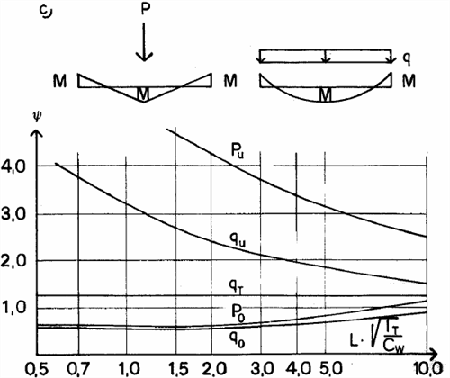
Mcr = ψ·Mvio
ψ ref. NS2 A5.5.2 Sect. a - d
D12.A.4.3 Determination of βz and βy
The equivalent moment factor β (for z and y) is calculated dependent on moment distributions as shown in the following table:
| Moment diagram | βM (βLT) |
|---|---|
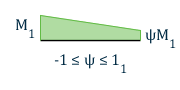
|
βM ψ = 1.8 - 0.7ψ |
|
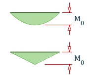
βM 0 = 1.3
βM 0 = 1.4 |

|
M0 = |Mmax| due to transverse load only ΔM = |Mmax| if the moment has the same sign ΔM = |Mmax| + |Mmin| if the moment changes sign |
The user can override the calculated factor with the following parameters:
| βy=SSY |
| βz=SSZ |
D12.A.4.4 Lateral buckling
The Ideal lateral buckling moment is calculated according to NS2 A5.5.2
concern double symmetric cross sections where y is given in NS fig. A5.5.2, (input parameter CB), L = member length for lateral buckling (input parameter UNL), Cw and Ix , see section 5.
For single symmetric cross sections, the ideal lateral buckling moment is
Where:
- α = distance from profile CoG to point where the load is acting, assumed to be on top flange.
The φ parameter (ref NS fig. A5.5.2.g) is controlled by the input parameter CB.

ψ-coefficients for a simple span beam

ψ-coefficients for a partially restrained beam
ψ-coefficients for a fully restrained beam
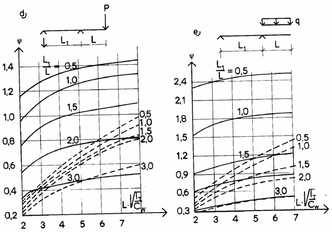
ψ-coefficients for the cantilevered beam with single loads and distributed loads. Dashed curves apply load on the surface.
D12.A.4.5 Stability check of pipe members
The stability criteria applied for members with pipe cross section is:
Where:
M z and M z are given in NS 5.4.2.
For the print output option TRACK 9.0 KE ≡ 1.0 and Mvd ≡ Md
D12.A.4.6 Angle profiles type RA (reverse angle)
The axial contribution to the total interaction ratio is checked according to the modified EECS-method, see NS A5.4.
The stability criterion is:
Where:
Nkyd and Nkzd are found from NS 3472 fig. 5.4.la C-curve for y- and z-axis, respectively.
For λ ≤ √(2)
λ eff = 0.60 + 0.57λ
For λ > √(2)
λ eff = λ
Where:
| λk = lk/i |
Possible lateral buckling effects and torsional buckling (NS A5.4.5) is not included in the code check. This has to be evaluated by the user separately.
D12.A.4.7 Stability check of members with tapered section
Stability of members with tapered cross section is calculated as described in section 3.1. The cross section properties used in the formulae are calculated based on the average profile height. (i.e., Iz, Iy values are taken from the middle of the member.)
D12.A.4.8 Lateral buckling for tension members
When compressive stress caused by large bending moment about strong axis is greater than tension stress from axial tension force, lateral buckling is considered as defined below.
| σa = N/A (+ tension, - compression) |
| σbz = ± Mz/Wz |
| Mwarp = | σa + σb | Wz for σa + σb < 0 (compression) |
| IR = Mwarp/Mvd + My,max/Myd ≤ 1.0 |