V. Roof Truss Axial Forces
To find the forces in the members of a truss structure due to fabrication defect in the length of one bar which is 0.75 cm too short.
Reference
C.K. Wang, Intermediate Structural Analysis, International Student Edition, 1983, McGraw Hill, Section 10.13, p.387
.
Problem
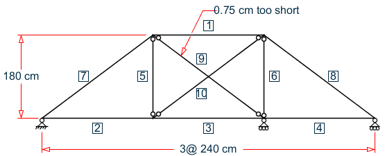
Structure to be solved as a truss. To achieve this in the STAAD model, instead of declaring them truss members, define them as frame members, and release MZ at both ends of all members. In the above figure, the area of cross section of the members is as follows.
1 TO 4 = 20 cm2
5, 6 = 24 cm2
7, 8 = 30 cm2
9, 10 = 15 cm2
Frame subject to temperature change
Comparison
| Member Number | Theory | STAAD.Pro | Difference |
|---|---|---|---|
| 1 | 280.56 (C) | -280.57 | none |
| 2 | 50.86 (T) | 50.86 | none |
| 3 | 127.99 (C) | -127.99 | none |
| 4 | 101.72 (T) | 101.72 | none |
| 5 | 134.14 (C) | -134.14 | none |
| 6 | 57.85 (C) | -57.85 | none |
| 7 | 63.57 (C) | -63.57 | none |
| 8 | 127.14 (C) | -127.15 | none |
| 9 | 287.13 (T) | 287.13 | none |
| 10 | 223.56 (T) | 223.56 | none |
STAAD Input
The file C:\Users\Public\Public Documents\STAAD.Pro 2023\Samples \Verification Models\02 Trusses\Roof Truss Axial Forces.STD is typically installed with the program.
STAAD SPACE EFFECT OF FABRICATION DEFECT - PRESTRAIN
START JOB INFORMATION
ENGINEER DATE 10-Oct-17
END JOB INFORMATION
*
* REFERENCE: INTERMEDIATE STRUCTURAL ANALYSIS, C.K.WANG
*     INTERNATIONAL STUDENT EDITION, 1983, MCGRAW HILL
*     SECTION 10.13, PAGE 387
*
UNIT METER KN
JOINT COORDINATES
1 2.4 1.8 0; 2 4.8 1.8 0; 3 0 0 0; 4 2.4 0 0; 5 4.8 0 0; 6 7.2 0 0;
MEMBER INCIDENCES
1 1 2; 2 3 4; 3 4 5; 4 5 6; 5 4 1; 6 5 2; 7 3 1; 8 2 6; 9 1 5; 10 4 2;
UNIT CM KN
MEMBER PROPERTY AMERICAN
1 TO 4 PRIS AX 20 IX 0.01 IY 0.01 IZ 0.01
5 6 PRIS AX 24 IX 0.01 IY 0.01 IZ 0.01
7 8 PRIS AX 30 IX 0.01 IY 0.01 IZ 0.01
9 10 PRIS AX 15 IX 0.01 IY 0.01 IZ 0.01
UNIT CM NEWTON
DEFINE MATERIAL START
ISOTROPIC MATERIAL1
E 2e+07
POISSON 0.3
END DEFINE MATERIAL
UNIT CM KN
CONSTANTS
MATERIAL MATERIAL1 ALL
* ALL MOMENTS RELEASED TO SIMULATE TRUSS ACTION
MEMBER RELEASE
5 6 9 10 START MZ
5 6 9 10 END MZ
*1 TO 10 START MZ
*1 TO 10 END MZ
SUPPORTS
3 PINNED
5 6 FIXED BUT FX MZ
LOAD 1
TEMPERATURE LOAD
9 STRAIN -0.75
PERFORM ANALYSIS
UNIT CM NEWTON
PRINT MEMBER FORCES
FINISHSTAAD Output
   MEMBER END FORCES    STRUCTURE TYPE = SPACE
   -----------------
   ALL UNITS ARE -- NEWT CM       (LOCAL )
  MEMBER  LOAD  JT     AXIAL   SHEAR-Y  SHEAR-Z   TORSION     MOM-Y      MOM-Z
      1    1     1 280565.47     -0.03     0.00      0.00      0.00      -4.05
                 2-280565.47      0.03     0.00      0.00      0.00      -2.71
      2    1     3 -50858.06      0.02     0.00      0.00      0.00      -0.38
                 4  50858.06     -0.02     0.00      0.00      0.00       4.02
      3    1     4 127991.16     -0.03     0.00      0.00      0.00      -4.02
                 5-127991.16      0.03     0.00      0.00      0.00      -2.67
      4    1     5-101716.24      0.01     0.00      0.00      0.00       2.67
                 6 101716.24     -0.01     0.00      0.00      0.00      -0.23
      5    1     4 134136.97      0.00     0.00      0.00      0.00       0.00
                 1-134136.97      0.00     0.00      0.00      0.00       0.00
      6    1     5  57849.78      0.00     0.00      0.00      0.00       0.00
                 2 -57849.78      0.00     0.00      0.00      0.00       0.00
      7    1     3  63572.59      0.01     0.00      0.00      0.00       0.38
                 1 -63572.59     -0.01     0.00      0.00      0.00       4.05
      8    1     2 127145.30      0.01     0.00      0.00      0.00       2.71
                 6-127145.30     -0.01     0.00      0.00      0.00       0.23
      9    1     1-287134.25      0.00     0.00      0.00      0.00       0.00
                 5 287134.25      0.00     0.00      0.00      0.00       0.00
     10    1     4-223561.55      0.00     0.00      0.00      0.00       0.00
                 2 223561.55      0.00     0.00      0.00      0.00       0.00