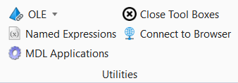
Utilities

Utilities


Image

|
Setting |
Description |
|
Display |
Used to display a bitmapped (raster) image in a window. |
|
Convert |
Used to make batch conversions of raster image files. |
|
Capture |
Used to take "screen shots" - to capture an image of the screen or a portion of the screen in a variety of graphical formats. |
|
Save Panorama |
Used to save an image as a panorama. |
|
Save Multiple |
Used to build an image script file that defines the names of the design files, views, output files, rendering options, and image formats of the image files being saved. |
|
Save Image |
Used to save the contents of a rendered or wireframe view to a file. |


Macros

|
Setting |
Description |
|
Used to run the selected macro. |
|
|
Used to record actions such as selecting tools, placing elements, opening and closing dialogs, and so on. |
|
|
Used to stop recording a macro. |
|
|
Displays a list of macros available in the currently loaded BMR and VBA projects. |
|
|
Opens the Editor in which you can edit the selected macro. |
|
|
VBA Manager |
Serves as OpenSite Designer 's integrated development environment (IDE) for VBA, allowing you to manage VBA projects. VBA macros are not embedded in DGN files, they are stored separately in .mvba files. |
|
Used to display a list of macros available in the currently loaded projects. |


Design History

|
Setting |
Description |
|
Commits changes to the design history. Increases the design history's revision number by one. |
|
|
Used to initialize design history for a DGN file. |
|
|
Set Revision Number |
Used to set the revision number to be used for the next commit. |
|
Tags |
Used to assign symbolic names to revisions in the design history. |
|
Audit Trail |
Used to display a record of history management actions, such as creation, combine, retire, or change in revision number. |
|
Restore |
Used to undo all changes to a collection of elements since a specific revision, thus restoring their state as of that revision. |
|
Combine |
(Available when combine=1 is set in the MS_DESIGN_HISTORY configuration variable) Used to delete a range of revisions, replacing them with a single, net revision. |
|
Disabled |
(Available when delete=1 is set in the MS_DESIGN_HISTORY configuration variable) Used to remove design history from a design file. |


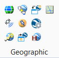
Geographic
|
Setting |
Description |
|
Coordinate System |
Opens the Geographic Coordinate System dialog, which is used to select a geographic coordinate system (GCS) from a library of predefined geographic coordinate systems. |
|
Global Positioning System (GPS) |
Opens the Global Positioning System dialog, which is used to interface with Global Positioning System (GPS) devices. |
|
Export Google Earth (KML) File |
Used to capture the terrain and imagery of the current Google Earth view. |
|
Capture Google Earth Image |
Used to capture the terrain and imagery of the current Google Earth view. |
|
Define Placemark Monument |
Used to associate a geographical location to a Monument point in a model. |
|
Synchronize Google Earth View |
Used to have Google Earth navigate to the current view. If Google Earth is not open when the tool is used, it will be opened automatically. |
|
Follow Google Earth View |
Used to match the active view to the current Google Earth view location. |
|
Google Earth Settings |
Used to control the settings and operation of the Google Earth tools. |
|
Play Camera Animation in Google Earth |
Used to play a camera animation in Google Earth. |
|
Open Location in Google Maps |
Used to open Google Maps with the selected location in the center of the map. |


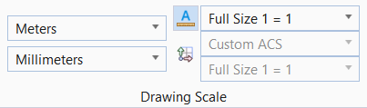
Drawing Scale
|
Setting |
Description |
|
Master Unit |
Allows you to set the Master Units component of working units. |
|
Sub Unit |
Allows you to set the Sub Units component of working units. |
| Annotation Scale Lock | Allows you to turn on a lock to the scale factors on the annotation scale. |
| Annotation Scale | Allows you to set the scale factor for text and dimensioning. |
| ACS Plane Lock | Allows you to forces each data point to lie on the XY-plane of the active auxiliary coordinate system, setting all Z-coordinates to zero. This concept applies only to 3D files. |
|
Auxiliary Coordinate System |
Allows you to define new x- and y- axes in your design plane and save them as an auxiliary coordinate system (ACS). |
|
Auxiliary Coordinate System Scale |
Allows you to set the Auxiliary Coordinate System scale factor. When active, elements are placed with the scale factor applied. |